Weldmatic Fabricator
Operators Manual
10
Model No. CP117-2, Iss C 05/07
Quality, Reliability, Performance
If the voltage is too low the wire will stub and
stutter, and there will not be a steady arc. If
the voltage is too high the arc will be long with
metal transfer occurring as a series of large
droplets.
Important:
Do not operate the Voltage
Control switches during welding.
The weld setting should be chosen to suit the
application and the thickness of the metal to
be welded. It is important to check that the
deposited weld provides sufficient strength to
suit the application.
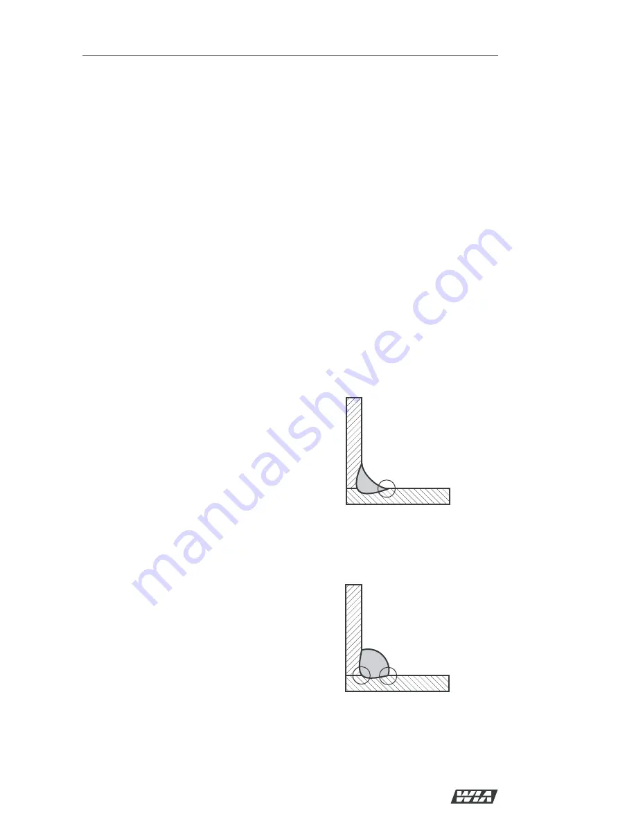
A “good” weld will have the characteristics
illustrated in Figure 4. The weld has penetrated
into the parent metal, fusing the root of the
joint where the two plates meet, and the weld
blends smoothly into the side walls.
A “bad” weld is shown in Figure 5. The weld
has not penetrated the joint root, and there is
poor side wall fusion. This lack of fusion would
normally be corrected by increasing the arc
voltage, or by increasing both wirefeed speed
and arc voltage to achieve a higher current
weld setting.
7 Basic Welding Information
Choice of Shielding Gas
The choice of shielding gas is largely
determined by the consumable wire to be used.
Many proprietary shielding gas mixtures are
available.
The recommended shielding gases for use with
the Weldmatic Fabricator are:
• Mild Steel
Argon +
5 to 25% Carbon Dioxide;
100% CO
2
• Aluminium
Argon;
• Stainless Steel Argon + 1 to 2% Oxygen.
Consult your gas supplier if more specific
information is required.
Shielding Gas Flow Rate
In G.M.A. welding, one function of the
shielding gas is to protect the molten weld pool
from the effects of oxygen in the atmosphere.
Without this protection the weld deposit
becomes ‘honeycombed’ in appearance, an
effect which is described as weld porosity.
In draft-free conditions the gas flow rate
required to give adequate protection is
typically 10-12 litres/min. In situations where
drafts cannot be avoided, it may be necessary
to increase this rate up to 20 litres/min, and/or
to provide screening of the work area.
Weld porosity can also be caused by air
entering the gas stream through a damaged
hose, loose gas connection, or from restriction
in the nozzle, such as from excess build-up of
spatter.
When welding aluminium, particular care
must be taken with all aspects of shielding gas
delivery and workpiece preparation in order to
avoid weld porosity.
Establishing a Weld Setting
Once the consumable wire type, wire size
and shielding gas have been chosen, the two
variables that are adjusted in order to obtain a
the desired weld setting are;
• Wirefeed speed,
• Welding arc voltage.
The wirefeed speed determines the welding
current; increasing the speed increases the
current, and decreasing it decreases current.
The selected wirefeed speed must be matched
with sufficient arc voltage; a speed increase
requires an increase of arc voltage.
Fig “Good” Weld
Fig 5 “Bad” Weld


