3.
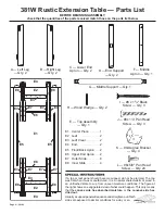
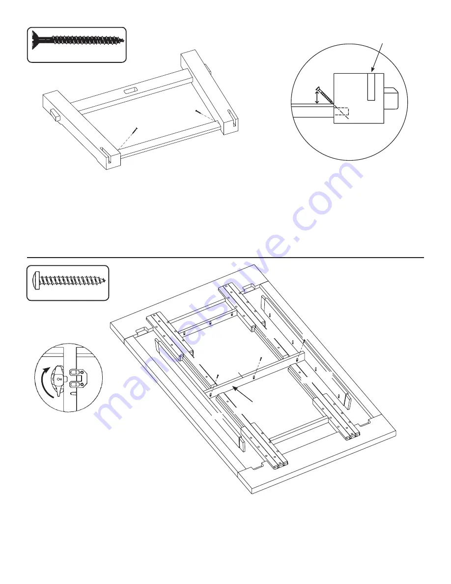
For added strength, insert a Screw (I) through the back side of the Lower End Apron (C) (the
side with the remaining mortise holes in the legs) into each leg (A & B). See FIGURE 3A. Start
the screw in the corner and at an angle so that it will not go through the other side of the leg. To
insert the screw at a proper angle, the screw head should be approximately 1/2" from the Lower
End Apron (C). See FIGURE 3B.
Repeat steps 2 – 3 for the other set of legs.
I
x 4
FIG. 3A
FIG. 3B
END VIEW
4.
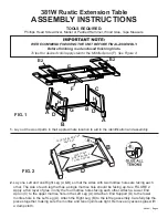
Lay Top Assembly (E) on a protected surface with the bottom facing up. Make sure both Ends
(E4) are pushed all the way in and locked in place. Do not insert leaves at this point. Place Middle
Apron (F) in the center of the table as shown in FIGURE 4. The Middle Apron (F) should be
centered between the Front/Back Aprons (E5) and have equal distance on either side from the
Inner Slides (E8). Secure the Middle Apron (F) with three Screws (J).
J
x 3
FIG. 4
I
I
B
A
D
C
I
Mortise Hole
1/2"
A
C
E4
E
E8
E8
E5
E5
E8
E8
E4
F
J
J
J
Page 4 — 381W
Stain Test
Area


