STOVE PREPARATION continued
Insert Model:
1. Refer to the shroud installation instructions included in the
shroud box.
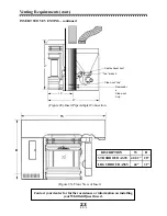
2. Installing the control board- the damper adjustment is
controlled by a cable mechanism. On insert stoves, the
control board assembly (see Figures 2 and 18) will need to
be removed from the side of the stove and attached to the
back of the shroud side panel. After attaching the left side
shroud panel to the stove, follow this procedure:
a) Remove the four lock-nuts from the back of the shroud
left panel and set them close by.
b) Use a 1/4" nut driver or socket to remove the two screws
that hold the control board assembly to the bottom side of
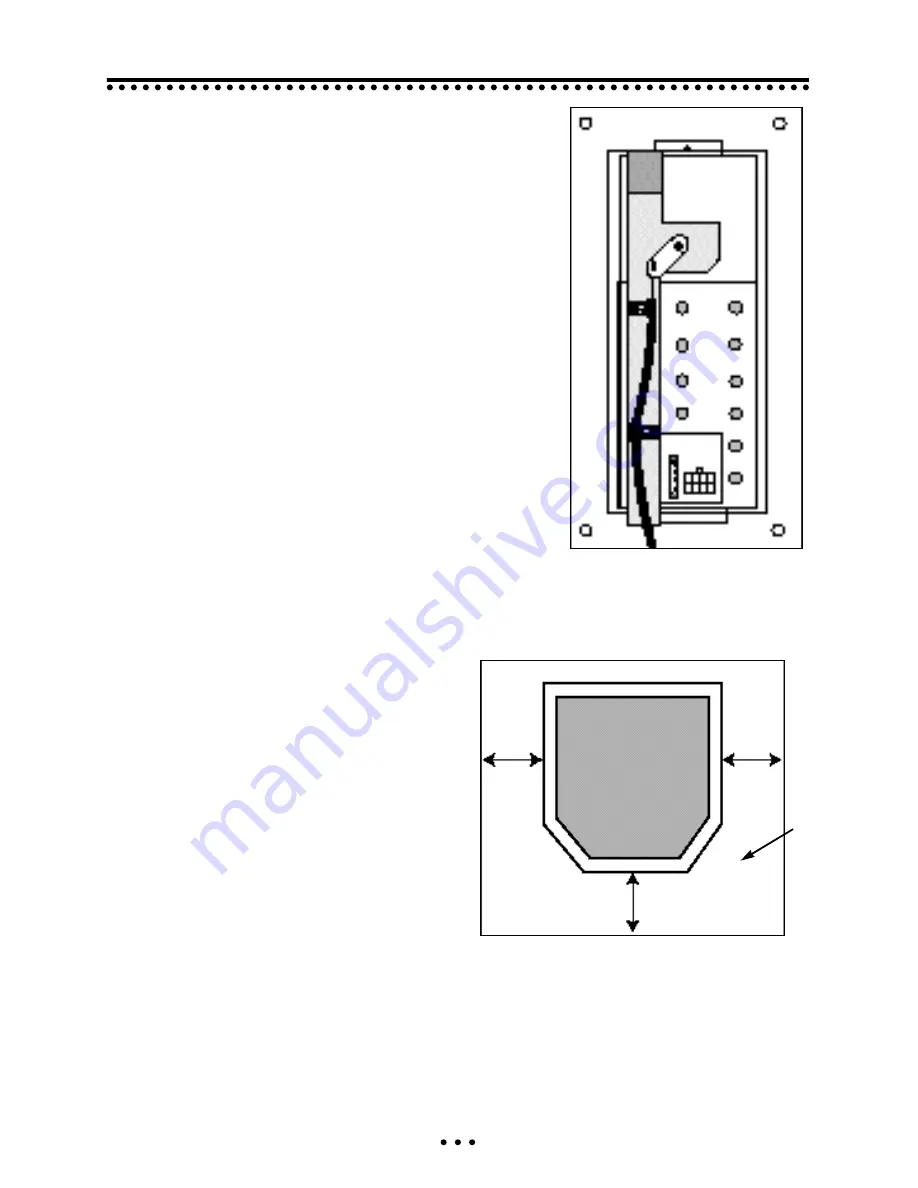
the stove. Without turning the control board assembly, slip
it over the four studs on the back of the left side panel
(see Figure 18).
c) Place the four lock-nuts back on the studs, and tighten
them with a 3/8" socket or nut driver.
d) With the damper control knob set to the lowest position of
the “LOW” Range (damper fully closed), look under the
auger tube, and verify that the cable is still hooked into the
damper control arm. Turn the Damper Control knob
through its full range to check for proper function.
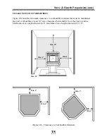
FLOOR PROTECTION
Your Whitfield pellet stove must be installed
on a non-combustible protective floor pad
(3/8" minimum thickness material), or on a
masonry hearth. The hearth or floor pad
must extend a minimum of 6" from the front
and both sides of the stove (as shown in
Figure 19), or to the nearest permitted corm-
bustible material if less than 6".
Stove & Hearth Preparation (cont.)
17
(Figure 19)
Floor Protection Requirements
(Figure 18)
Control board on Shroud Panel
Non-
combustible
Floor
protector
TOP VIEW OF STOVE ON FLOOR PAD
Floor protector must extend at least 6"
from the front and sides of the stove.
6
”
6
”
6
”


