Page
22 of 40
Issue 2
13/12/99
PETS-2 Crossing Telephone System
QUICKFIX INSTALLATION HANDBOOK
22
e) If the left hand Connector Plate has been temporarily fitted - remove it now!
f) Install the frame back into the case (now fixed to the wall). Re-fit the internal earth tag.
Loose fit the M6 hexagonal bolts (starting with the top ones), fit the bottom left hand bolt
but this will be kept loose for now. Support the frame with one hand whilst re-assembling.
Make sure the frame is correctly positioned and tighten the three hexagonal bolts
(excluding the lower left side bolt - the earth bolt). Refer to section 5.5 before continuing.
a) Re-fit
the
Connection Plate,
making sure to keep
the rubber gasket
between the plate
and the outside of
the case. NOTE -
THIS GASKET IS A
NECESSARY
PART OF THE
SIGNAL BOX UNIT
SINCE IT
ESTABLISHES
THE DISTANCE
BETWEEN
CONNECTOR
PLATE AND
CONNECTOR PCB. THE THICK FOAM RUBBER GASKET INSIDE THE CONNECTOR
PLATE WELL, IS ONLY USED ON THE LEVEL CROSSING UNIT. Fit six M3 screws
and washers exclude the middle two required by the Connector Retention bracket.
b) Refer to section 5.8.1 and wire the 9 pin ‘D’ connector onto an appropriate length of
0.6mm telephone cable, to reach the power supply unit. NOTE: 0.5/0.6mm
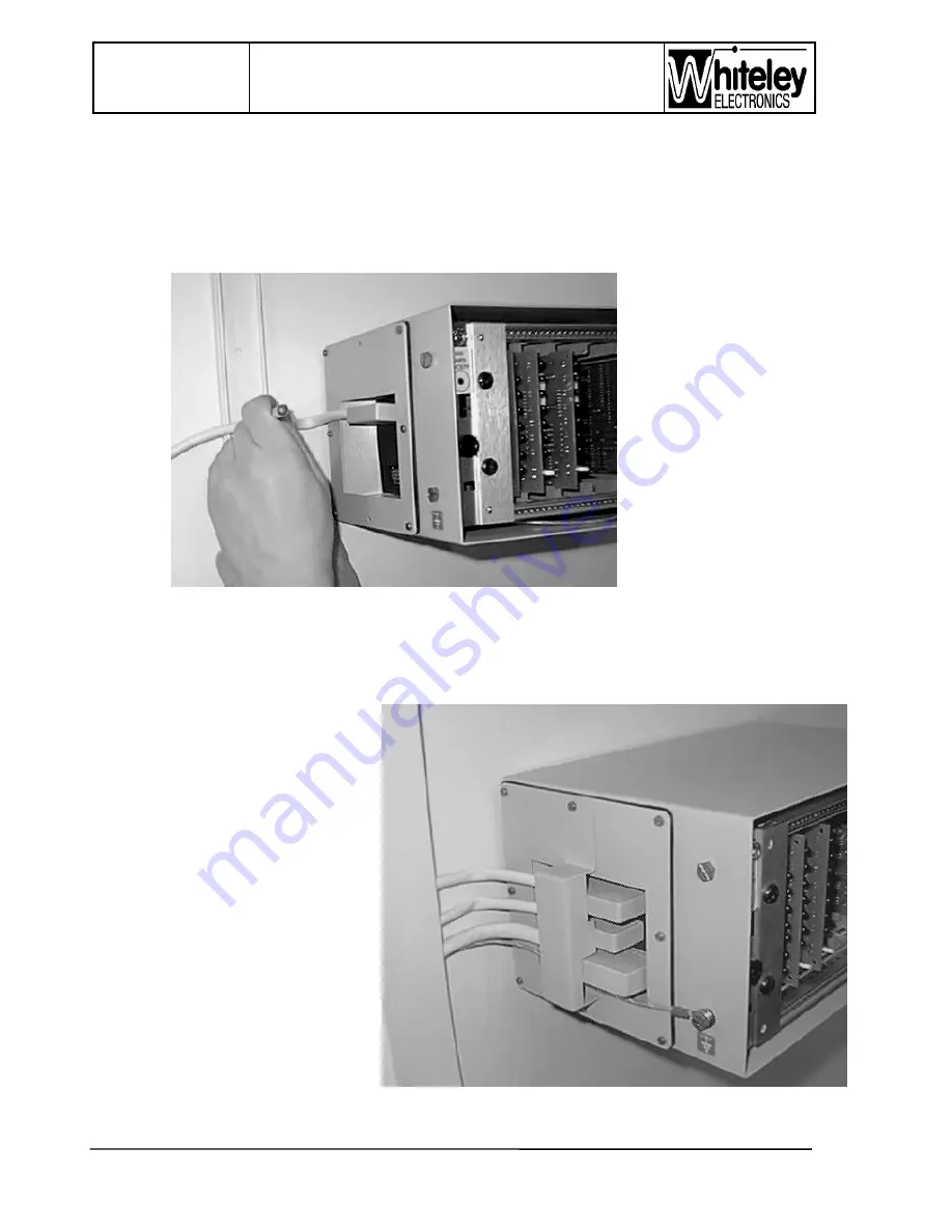
a)
Install each connector and
position the cables in a gentle
bend to the cable trunking, or
position into cable clips on the
wall. Making sure that the
connectors are fully mated and
aligned. Now fit the Connector
Retention bracket and its fixing
screws. Tighten the screws.
b)
Now that the cables are
correctly positioned in the
trunking (or clipped to the wall),
the Junction Box can be
properly fixed to the wall.
Wall fixing is now complete.
5.5 Safety Earth


