background image

44

Installing the pipes

Install the drain fitting and the drain hose (for model
with heat pump only).
Condensation is produced and flows from the
outdoor unit when the appliance is operating in the
heating mode. In order not to disturb neighbours
and to respect the environment, install a drain fitting
and a drain hose to channel the condensate water.
Install the drain fitting and rubber washer on the
outdoor unit chassis and connect a drain hose to it
as shown in the figure.
Use suitable connecting pipes and equipment for the refrigerant R410a.
The connecting pipes must not exceed the maximum lengths 10 m.
Wrap all the refrigerant pipes and joints.
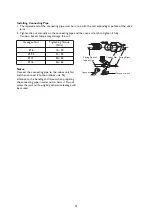
Tighten the connections using two wrenches working in opposite directions.

Air Purging

Humid air left inside the refrigerant circuit can cause
compressor malfunction. After having connected the
indoor and outdoor units, bleed the air and humidity
from the refrigerant circuit using a vacuum pump.
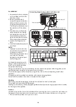
1. Unscrew and remove the caps from the 2-way

and 3-way valves.2. Unscrew and remove the cap
from the service valve.

3. Connect the vacuum pump hose to the service

valve.

4. Operate the vacuum pump for 10-15 minutes

until an absolute vacuum of 10 mm Hg has been
reached.

5. With the vacuum pump still in operation, close

the lowpressure knob on the vacuum pump
coupling. Stop the vacuum pump

6. Open the 2-way valve by 1/4 turn and then close

it after 10 seconds. Check all the joints for leaks
using liquid soap or an electronic leak device.

7. Turn the body of the 2-way and 3-way valves.

Disconnect the vacuum pump hose.

8. Replace and tighten all the caps on the valves.

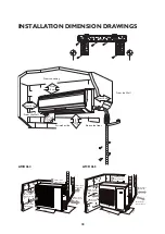
INSTALLATION DIMENSION DIAGRAM

The installation must be done by trained and qualified service personnel with reliability according to this
manual.
• Contact service centre before installation to avoid the malfunction due to unprofessional installation.
• When picking up and moving the units, you must be guided by trained and qualified person.
• Ensure that the recommended space is left around the appliance.

Diameter (mm)

Twisting moment (Nm)

Ø 6

15~20

Ø 9.5

35~40

Ø 12

45~50

Ø 16

60~65

Ø 19

70~75

Vacuum pump

Vacuum pump

Indoor unit

Refrigerant fluid direction of flow

3-way valve

Service
inlet

(2) Turn
(8) Secure

(7) Turn to open fully

(2) Turn

(2) Turn

2-way valve

(6) Open 1/4 turn

(7) Turn to open fully

valve cap

valve cap

(8) Secure

(8) Secure

Connect to
indoor unit

Содержание AMD 064

Страница 1: ...t as this will decrease the effect of the air conditioner or cause it to shut down or even catch fire Spray cans chemicals and gas tanks must be placed at least 1m away from the indoor and outdoor unit they could cause fire or explosion Make sure to mount the outdoor unit on a sturdy base If the base is damaged and unsteady the unit could fall and cause injury Do not stand or place anything on the...

Страница 2: ...s very quickly Use this air conditioner with other heating equipment when outdoor temperatures are extremely low Defrost The outdoor unit heat exchanger may frost when the outdoor temperature is low humidity is high and the air conditioner has been running for some time resulting in inefficient heating In this case the appliance automatically defrosts and heating is suspended for 6 10 minutes Both...

Страница 3: ...8 Sealing tape 9 Indoor outdoor power cord 10 Drain Pipe 10 9 5 6 7 8 2 1 4 3 6 Air inlet Air outlet Remote Control Indoor Unit Outdoor Unit Heat Cool Temperature On Dehumidify Signal receiver Air inlet Air outlet Images in the user instructions are based on external views of standard models shape and design vary according to the model ...

Страница 4: ...he CLOCK icon will start to blink and you can set the time Description and Function of Remote Control Keys Note Be sure to point the remote control towards the signal receiver Check that there is no obstacle between the remote control and signal receiver Do not drop or throw the remote control Do not drop any liquid onto the remote control or expose it to direct sunlight or extremely hot temperatu...

Страница 5: ... louver swings back and forth in all the five places as shown in the figure TIMER ON key Timer On setting ON flashes and will conceal numeral segment become timer on setting status Pressing or could adjust the numeral segment of time increase or decrease 1 minute per time within 5 seconds If you hold pressing or the numeral will change quickly after 2 second The way of the change is in the first 2...

Страница 6: ...once will activate the SLEEP function and the SLEEP icon will appear Pressing again disables the SLEEP function On changing mode or starting stopping the unit the SLEEP function will be cancelled automatically The set temperature will rise max 1 C if the appliance operates in cooling mode for two hours then it will remain constant if room temperature is 26 C or above set temperature will not chang...

Страница 7: ...use new batteries with old batteries or different types of batteries as this may cause the remote control to malfunction If you do not expect to use the remote control for some time take the batteries out to prevent leakage of battery acid in the remote control Operate the remote control within effective range Keep the remote control at least 1 meter from any TV set or hi fi equipment If the remot...

Страница 8: ...shown by the arrow Pull the slots at the two ends of the front panel with force to remove the front panel 2 Cleaning the front panel Wash with a soft brush soaked in water and neutral detergent Wipe off the water and dry the panel Note To avoid discoloring or deformation do not wash with hot water over 45 C 3 Replacing the front panel depending on the model Place the rotary holder on two ends of t...

Страница 9: ...filter as shown by the arrow Clamp the cover of the front panel securely Checks before Seasonal Use 1 Check the air inlet outlet on indoor and outdoor units for any blocking 2 Check the grounding cable for reliability 3 Check the battery of the remote control for replacement 4 Check the mounting frame of the outdoor unit for damage If damaged contact a Whirlpool Authorized Service Center Maintenan...

Страница 10: ...ity are high This is because the indoor air is cooled quickly After a short time the fog will disappear as the indoor temperature and humidity decrease You may hear a slight crack when the air conditioner is started or stopped This is the sound of friction caused by expansion of the front panel or other parts due to the change of temperature Air conditioner does not run Is there a power failure Is...

Страница 11: ...exchanger has more frost the air conditioner will activate the auto defrost function and the indoor unit will stop air blowing for 6 10 minutes During defrost water or steam may flow from the outdoor unit In dehumidify mode the fan on the indoor unit may stop to prevent evaporation of condensing water and rise of temperature Moisture on outlet grill If the air conditioner is left running in high h...

Страница 12: ...nsation water can be easily discharged and the outdoor unit can be easily connected 3 Install out of the reach of children 4 Choose a place capable of bearing the weight of the indoor unit without increasing noise and vibrations 5 Ensure sufficient clearance and space for service and maintenance ensure the indoor unit is at least 2 3m from the floor 6 Choose a position at least 1 meter from any TV...

Страница 13: ... As the air conditioning unit is a Class 1 electrical appliance reliable grounding measures must be taken 2 The yellow and green cable inside the air conditioner is for grounding and must not be used for other purposes or cut Do not tighten with tapping screws this could cause electrocution 3 The user power supply shall have a reliable grounding terminal It is prohibited to connect the grounding w...

Страница 14: ...cm Air intake side AMD 064 AMD 065 50 cm or more Space to the cover 30 cm or above Space to the cover 30 cm or above Air inlet side 50 cm or above Space to the wall 200 cm or above Air outlet side 50 cm or more Space to the cover 30 cm or above Space to the cover 200 cm or above Air outlet side 50 cm or above Space to the wall 30 cm or above Air inlet side ...

Страница 15: ...l a tapered hole Ø 55 2 To prevent the fitting pipe and the cable passing through the wall from being harmed and also to protect the hollow wall from rats it is necessary to install a wall pipe Installing Drainage Pipe 1 The flexible drainage pipe must be tilted downward to allow the water to drain 2 Make sure not to kink hump or distort drainage pipe in the layout and not to immerse the outlet in...

Страница 16: ...necting cable Improper fastening may allow dust or water to enter or expose connecting terminal directly to external forces and fire or electrocution could occur Installing Indoor Unit Fitting pipe can come from four directions i e right rear right left and rear left 1 When installing the pipe on the left or right side trim off any extra pipe left at the pipe outlet stub on the base of the unit Se...

Страница 17: ...orque may damage the nut Notes Connect the connecting pipe to the indoor unit first and then connect it to the outdoor unit Pay attention to the bending and layout when preparing the connecting pipe in order not to harm it Do not screw the joint nut too tightly otherwise leakage will be caused Hexagon Nut Tightening Torque Nlm Ø 6 15 20 Ø 9 5 31 35 Ø 12 50 55 Ø 16 60 65 Fitting Pipes of Indoor Uni...

Страница 18: ... malfunction of some electric components After fixing cable ensure that leads between connection to fixed point have some space The connection pipes and the connection wirings of the units must be corresponding to each other respective The appliance shall be installed in accordance with national wiring regulations Do not install the outdoor unit where it is exposed to the sunlight Handling After h...

Страница 19: ...fixing cable ensure that leads between connection to fixed point have some space The connection pipes and the connection wirings of the units must be corresponding to each other respective The appliance shall be installed in accordance with national wiring regulations Do not install the outdoor unit where it is exposed to the sunlight Handling After having removed the packaging check that the cont...

Страница 20: ...cuum pump hose to the service valve 4 Operate the vacuum pump for 10 15 minutes until an absolute vacuum of 10 mm Hg has been reached 5 With the vacuum pump still in operation close the lowpressure knob on the vacuum pump coupling Stop the vacuum pump 6 Open the 2 way valve by 1 4 turn and then close it after 10 seconds Check all the joints for leaks using liquid soap or an electronic leak device ...

Страница 21: ...ibrate or make noise Has gas leakage been checked May cause unsatisfactory cooling heating effect Is the thermal insulation of the unit sufficient May cause unsatisfactory cooling heating effect Is drainage smooth May cause condensation and dripping Is the main supply voltage the same as the rated voltage specified on the nameplate The unit may break down or components may burn out Are the lines a...

Отзывы: