43
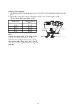
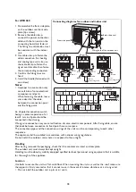
For AMD 065:
1. Disassemble the front side plate
on the outdoor unit front side
plate (4pc screw).
2. Remove the cable clamp,
connect the power connection
cable with the terminal on the
connecting board and fasten it.
The fitting line distribution must
be consistent with the indoor
unit.
3. Use cable clamp to fasten the
cable connection. For heating
and cooling type unit, also use
the cable clamp to fasten the
signal control cable, then fasten
the corresponding connectors.
4. Confirm the fitting lines are
fixed.
5. Install the handle (fastened with
one screw).
Notes:
• Improper line connection may
cause failure of some electrical
components and parts
• When fastening the cable, leave
some slack for the cable
between the connection point
and the fixing point.
An all-pole disconnection switch
having a contact separation of at
least 3 mm in all pole should be
connected in fixed wiring.
Wrong wire connection may cause malfunction of some. electric components. After fixing cable, ensure
that leads between connection to fixed point have some space.
The connection pipes and the connection wirings of the units must be corresponding to each other
respective.
The appliance shall be installed in accordance with national wiring regulations.
Do not install the outdoor unit where it is exposed to the sunlight.
Handling
After having removed the packaging, check that the contents are intact and complete.
The outdoor unit must always be kept upright.
Handling must be done by suitably equipped qualified technical personnel using equipment that is suitable
for the weight of the appliance.
Location
Use bolts to secure the unit to a flat, solid floor. When mounting the unit on a wall or the roof, make sure
the support is firmly secured so that it cannot move in the event of intense vibrations or a strong wind.
• Do not install the outdoor unit in pits or air vents.
L
N
To unit A
Back side panel
To unit B
Blue
Black
YEGN
Brown
Blue
Black
YEGN
Brown
Brown
Blue
YEGN
Power
connecting cord
Power
connecting cord
To the power supply
POWER
Connecting diagrams for oudoor and indoor unit
Front side panel
Wiring hole of the outdoor unit

