Page 2
BLACK
WHITE
FUSE
10 AMP
+ 12 VOLTS
GROUND
CHASSIS
SUITABLE
(SP/ST)
SWITCH
12 VDC
To mount the PierceAlert™ in front of the
power supply on a 48” and 52” lightbar.
1.
Disconnect the lightbar from its power source and wait at
least 15 minutes before proceeding any further
2.
Remove both endcaps from the extrusion.
3.
Slide all lenses and dividers out of the extrusion.
4.
Remove the Phillips-head screws or stand-offs
(depending on which of these your lightbar is equipped
with) from the power supply.
5.
Remove the power supply from the extrusion. Do not
disconnect the power supply from the lightbar harness
cables.
6.
Remove the filler panels from either end of the power
supply mounting area. Please note that not all lightbars
will have these filler panels.
7.
Remove the two (2) power supply mounting brackets by
rotating them 90 degrees.
Note:
If one of these brackets contain a fuse, do
not remove that bracket!
8.
If one of the power supply mounting brackets contains a
fuse, remove the two Phillips-head screws that secure
the adjoining reflector to it’s mounting bracket.
9.
Remove the existing reflector mounting bracket from the
extrusion by rotating it 90 degrees.
10. Slide the power supply mounting bracket with the fuse
into the area where the reflector mounting bracket was
located. This will replace the old reflector mounting
bracket.
11. The next step is dependent upon how your lightbar is
equipped:
If your lightbar has a drip cover attached to the power
supply, remove the screws that secure this cover to the
power supply (Fig. 3). Remove and discard the drip
cover and return the screws to their original position in
the power supply.
or
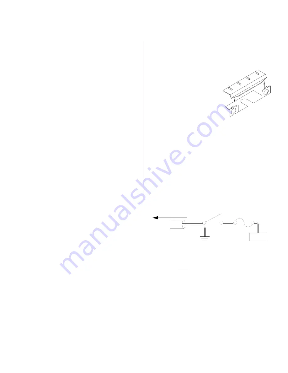
If your lightbar has a protective housing fastened to the
extrusion behind the power supply, trim this housing as
shown in FIg. 1.
12. Remove the reflector assembly
that is located above the cable
exit hole in the extrusion.
13. If a matrix board is not located
near the cable access hole, skip
to step #16.
14. Connect one end of the
PierceAlert-to-Matrix™ harness
cable
(supplied)
into
an
available option port on the
matrix board.
15. Route this harness cable to the PierceAlert mounting
area.
16. If there are no available option ports on the matrix board,
or if there is no matrix board present, route the two-
conductor harness cable up through the cable access
hole, into the extrusion and directly to the PierceAlert
mounting location.
17. Route this two-conductor cable along the same path as
the existing input cable for your lightbar, and connect it to
either an existing switch-head or to a user supplied
switch. Refer to the wiring diagram for details.
18. Return the reflector to its mounting area in front of the
cable access hole and secure with the original screws.
19. Now secure the reflector (referenced in steps 9 & 10) to
its new mounting bracket with it’s original screws.
20. Install the metal (not plastic), recessed power supply
mounting brackets that are included in this kit. Be sure
that these are positioned in the power supply mounting
area.
TO LIGHTBAR
Fig. 2
Fig. 1


