P84577 G
Sheet 10 of 14
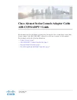
5.4 SPB-320 Wiring
Figure 13 shows the proper wiring for the two SP4-APS modules attached to the top SPB-160 module in the SPB-320. All
other wiring for the lower SPB-160 module is done the same way as the top module.
N
L
PS
PS+
_
F1
GND
E1
P82
798 R
E
V.
C
L
W5
W8
SW1
J2
R23
W7
D28
J1
D33
D24
D22
W10
D27
D26
D32
D31
D77
D76
D34
W4
W6
D75
J3
D59
F2
F1
TB6
TB5
TB4
TB1
TB2
AUX
TRB
TROUBLE
AMP TRB
GF
EXP OPEN
EXP SHORT
AUD1 OPEN
AUD1
SHORT
EXP OUT
AC
AC TRB
BAT TRB
LVL
N
AC
DC IN
DC OUT
BATTERY
AUD2 OUT
AUD1 OUT
STB2 OUT
STB1 OUT
EXP OUT
SPARE
C
NO
NC
T
R
B
AUX RET
AUX IN
AUD RET
AUD IN
J4
J5
AUD2 OPEN
AUD2 SHORT
D30
D29
TRANSFORMER
25
70
25
70
25
70
25
70
Audio Zones Out
PO
W
E
R
SU
PPL
Y
SW1 = NAC
EX1 and EX2 are not used when the SP4-APS
is connected to an Audio Booster.
Terminate as follows:
"CLASS A": Jumper to , and to .
"CLASS B" 10K Ohm EOLR across each EX zone.
10K Ohm
EOLR
OUT
IN
OUT
IN
OUT
IN
24 VDC
AUDIO
RS-485
ALARM
POWER
TROUBLE
Z1
Z2
Z3
Z4
EX1 EX2
IN
CLASS
B
A
SW
2
SP4-APS
JP
1
NAC
CC
SW1
TB1
TB2
TB7
TB6
TB5
TB4
TB3
JP1
Shorted = 70Vrms
Open = 25Vrms
D3
7
D3
2
D3
6
D3
5
D4
1
D3
3
D4
2
D4
3
D3
8
D3
4
D3
9
D4
0
D44
D45
OUT
IN
OUT
IN
OUT
IN
24 VDC
AUDIO
RS-485
ALARM
POWER
TROUBLE
Z1
Z2
Z3
Z4
EX1 EX2
IN
CLASS
B
A
SW
2
SP4-APS
JP
1
NAC
CC
SW1
TB1
TB2
TB7
TB6
TB5
TB4
TB3
JP1
Shorted = 70Vrms
Open = 25Vrms
D3
7
D3
2
D3
6
D3
5
D4
1
D3
3
D4
2
D4
3
D3
8
D3
4
D3
9
D4
0
D44
D45
Figure 13:
Wiring Diagram
For Connecting Two SP4-APS Splitters To One Of The Two SPB-160 PC Boards IN An SPB-320.