IsReg2001NC-0 Rev. 051011-2
14-30
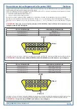
Description of the connections made on the OBD connector
English
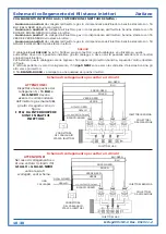
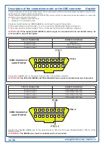
Connect a hand-held tester (CODE AEB214), and check the type of connection.
If the tester reads connection types 1,2, or 3, proceed by following the diagram in figure 1.
If the tester reads connection types 6,7,8 or 9, proceed by following the diagram in figure 2.
ATTENTION:
If the tester (CODE AEB214) reads a type of connection that is not stated above, do
not connect to any of the signals.
TYPE OF CONNECTION
CONNECTION DETAILS
Connection type 6
CAN Standard 250 Kbps
Connection type 7
CAN Extended 250 Kbps
Connection type 8
CAN Standard 500 Kbps
Connection type 9
CAN Extended 500 Kbps
Connect the GREEN wire to the signal found on PIN 7 of the OBD connector.
ATTENTION:
The YELLOW-GREEN and YELLOW-GREY wires must be isolated and not connected.
PIN7
1
8
9
FIG.1
16
Connect the YELLOW-GREEN wire to the signal found on PIN 6 and the wire YELLOW-GREY to PIN 14 of the
OBD connector.
ATTENTION:
The GREEN wire must be isolated and not connected
PIN6
1
8
9
FIG.2
16
PIN14
Through connection to the vehicle’s OBD socket, this new generation of GAS control units makes it possible to acquire infor-
mation useful for properly setting up the vehicle.
Several carburetion parameters acquired from the PETROL control unit can be seen using the special software for connecting
the GAS control unit to the PC, such as:
Carburetion calibrators (Fast and Slow).
•
Voltage on the rear lambda probe.
•
TYPE OF CONNECTION
CONNECTION DETAILS
Connection type 1
ISO 9141-2
Connection type 2
KWP-2000 Fast Init
Connection type 3
KWP-2000 Slow Init
OBD Connector
seen frontal
OBD Connector
seen frontal


