background image

30


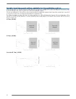
Aeraulic head losses and options available for the ventilating section

With the exception of units for which oversize fans are required, as standard, the units are designed considering that, 

at the nominal air flow rate, the fans work with null available pressure.
If there are obstacles to free air flow, you should consider the additional aeraulic head losses that will cause a reduction 

of the air flow rate and a consequent deterioration of performance.
The following diagrams show the trend of cooling capacity (P

C

), EER, total absorbed power (P

abs

) and reduction of the 

maximum external air temperature in chiller operating mode, depending on the aeraulic head losses that the fans will 

have to overcome.

AC fans (Ø 630)

EC fans (Ø 630)

Oversize EC fans (Ø 630)

Содержание Zeta Rev HE FC

Страница 1: ...igurations LN low noise unit NG unit without glycol on user circuit Strengths Patented free cooling system Reduced refrigerant charge Advanced Bluethink controller with integrated web server Multilogic Multifree functionality for multi unit systems Blueye supervision system Flowzer system with variable water flow rate Glycol free version available ...

Страница 2: ......

Страница 3: ...ecifications 18 Zeta Rev HE FC 18 Zeta Rev HE FC NG 19 Electrical specifications 20 Pump data 21 User side exchanger flow rate fields 22 Operating limits 23 Noise levels 24 Installation advice 26 Water characteristics 26 Glycol mixtures 26 Minimum water content in the system 27 Installation site 28 Installations that require the use of treated coils 29 Aeraulic head losses and options available fo...

Страница 4: ...2 ...

Страница 5: ...TA REV HE FC Chiller only mode When the ambient temperature is higher than the tem perature of the water returning from the system all the required cooling capacity must be produced by the com pressors In this mode the damper that controls the air flow rate at the free cooling coil is fully closed whereas the one in front of the condensing coil is fully open The 3 way valve bypasses the free cooli...

Страница 6: ...ferred to the system water through a decoupling exchanger This allows the glycol water circulating in the free cooling cir cuit to be separated from the system water that therefore does not need the addition of antifreeze The water leaving the decoupling exchanger will be the water that enters the evaporator Since the water is pre cooled the amount of capacity required of the chiller sec tion will...

Страница 7: ...e chiller free cooling the fans operate at full speed and condensation control is done by mod ulating the opening of the damper in free cooling mode the damper is fully closed so en suring the full flow rate at the free cooling coil alone FREE COOLING COIL The free cooling exchanger consists of a row coil with cop per tubes and aluminium fins Refer to chapters Installation advice and Description o...

Страница 8: ... from the outside All the electrical cables inside the panel are numbered and the terminal board dedicated to the customer s connec tions is coloured blue so that it can be quickly identified in the panel Power supply 400V 3 N 50Hz for models from 3 2 to 10 2 400V 3 50Hz for models 12 2 and 13 2 CONTROL BLUETHINK Main controller functions The microprocessor control allows the following functions w...

Страница 9: ...ff valves up stream and downstream of it a paddle flow switch to protect the free cooling circuit water safety valve to protect the free cooling circuit expansion vessel with water pressure gauge to protect the free cooling circuit For this version the intermediate heat exchanger is always in series with the user side heat exchanger and therefore the head losses inside the machine do not change wi...

Страница 10: ...commutated motor of the fans and is supplied as standard RIC Liquid receiver The adoption of this accessory always guarantees correct feeding of the expansion valve even when the unit is subjected to wide external air temperature ranges RPP Refrigerant leak detector with automatic pump down With this accessory a refrigerant leak detector is placed inside each compressor compartment Detection of a ...

Страница 11: ...ernal air temperature changes with a further reduction in electrical absorption and noise emission VEM Oversize EC fans With this accessory oversize EC fans with electronically commutated brushless motor are used for the ven tilating section These guarantee very high efficiency levels for all working conditions Through a 0 10V ana logue signal sent to each fan the microprocessor carries out conden...

Страница 12: ...ith integrated hydraulic module allow a certain level of available discharge head point A to be obtained under nominal flow rate conditions Qd But the actual head loss level of the system e g characteristic curve R normally causes the pump to find a different equilibrium point point B with a flow rate Qr higher than Qd In this condition besides having a different flow rate from the nominal flow ra...

Страница 13: ...ring summer operation and not during winter operation The use of this accessory also allows the pump speed to be adapted to possible fouling of the filter on the hydraulic circuit FLUS Flow switch instead of the water differential pressure switch As an alternative to the differential pressure switch standard flow sensor it is possible to request the paddle flow switch as accessory This detects whe...

Страница 14: ...formation recorded by the temperature probes installed on the delivery and return man ifolds of the system with the master unit a capacity request is generated that is distributed among the units connected in the Multilogic network according to settable priority and optimization logics If communication between the units fails or if the master is off line the slave units can continue to work ac cor...

Страница 15: ...ng a rotation on the hours of operation RIF Power factor correction to cosφ 0 9 With this accessory an electrical control panel containing power factor correction condensers to bring the cosφ of the unit to being greater than 0 95 is supplied loose The condensers should be connected by the customer to the electrical control panel of the unit in the specially prepared terminal board Besides reducin...

Страница 16: ...nic soft starter If the unit is equipped with accessory Power factor correction to cosφ 0 9 this last will be electro mechan ically connected only at the end of the acceleration ramp of the soft starter SQE Heater for electrical control panel Electric heaters are positioned inside the electrical control panel and these prevent the formation of ice or condensation inside it TERM Remote controlled u...

Страница 17: ...e outlet or an industrial kitchen or a solvent extraction fan in a small craft business Protective treatment of the exchanger is strongly recommended if at least one of the points below is verified there are obvious signs of corrosion of the exposed metal surfaces in the installation area the distance from the coast is less than 20 km the prevailing winds come from the sea towards the unit the env...

Страница 18: ...t causes the formation of a solid uniform deposit on the exchanger The function of this deposit will be to protect the aluminium from corrosion without penalising its thermophysical properties The choice of whether or not to treat the exchanger should be made in relation to the environment in which the unit is to be installed and through observation of other structures and machinery with exposed m...

Страница 19: ...pes without refrigerant charge untested covered by the warranty only if reassembled and screwed together by personnel authorized by the factory RAAL Cu Al coils This accessory uses finned pack coils with copper tubes and aluminium fins instead of microchannel coils SLIT Special pallet skid for container shipment The unit is placed on a skid that makes the container loading and unloading operations...

Страница 20: ...65 147 203 186 193 168 198 191 185 Available head with FC ON kPa 176 151 129 184 163 179 151 178 165 156 Hydraulic module 2P Available head with FC OFF kPa 174 148 125 193 174 173 142 188 178 170 Available head with FC ON kPa 162 134 107 173 151 159 125 168 153 141 Noise levels Sound power level of basic unit 5 dB A 78 79 79 80 81 82 83 84 86 87 Sound pressure level of basic unit 6 dB A 46 48 48 4...

Страница 21: ...mp model P1 P1 P1 P1 P1 P2 P2 P2 P2 P2 Available head 1P kPa 194 174 172 207 192 190 197 192 178 168 Available head 2P kPa 185 162 157 199 183 176 180 185 169 158 Noise levels Sound power level of basic unit 5 dB A 78 79 79 80 81 82 83 84 86 87 Sound pressure level of basic unit 6 dB A 46 48 48 48 49 50 51 52 54 55 Sound power level of LN version 5 dB A 76 77 77 78 79 80 81 82 84 85 Sound pressure...

Страница 22: ... 95 Maximum inrush current MIC 3 A 216 267 273 321 329 Maximum inrush current with soft starter MIC 4 A 146 177 183 212 220 Power supply V ph Hz 400V 3ph N 50Hz Power supply for auxiliary circuits V ph Hz 230V 24V 1ph 50 Hz Suggested line section 5 mm 25 25 35 50 50 Suggested line protection 6 NH00gG 100A NH00gG 100A NH00gG 125A NH00gG 160A NH00gG 160A Electrical specifications for fans Rated powe...

Страница 23: ...21 PUMP DATA Model Rated power Rated current Qmin Qmax kW A m h m h P1 1 9 4 2 7 18 P2 3 0 6 1 12 42 ...

Страница 24: ...s come within the allowed flow rate ranges specified below If the design conditions require a water flow rate that does not come within the allowed operating range you must contact our sales department that will identify the most suitable solution for the specific application ZETA REV HE FC Qmin Qmax m h m h 3 2 4 5 13 4 4 2 5 1 15 3 5 2 6 1 18 2 6 2 6 5 19 5 7 2 7 4 22 3 8 2 8 9 26 6 9 2 10 2 30 ...

Страница 25: ...on of the unit is guaranteed only by AC fans BK For LWTu below 3 C it is mandatory to fit the Brine Kit accessory For LWTu below 5 C it is compulsory to use suitable percentages of antifreeze additives glycols to prevent ice formation in the exchanger The inlet and outlet temperatures of the user side exchanger must be given on ordering to allow correct setting of the alarm parame ters and verific...

Страница 26: ... 70 39 69 37 67 36 62 31 76 44 4 2 77 45 76 45 68 37 72 40 71 40 71 40 68 37 63 32 77 46 5 2 77 45 76 45 68 36 72 41 72 41 71 39 68 36 63 32 77 46 6 2 77 46 76 45 68 36 70 39 73 41 73 41 69 37 66 34 78 46 7 2 77 46 76 45 68 36 73 41 73 42 73 42 70 38 65 34 79 47 8 2 79 47 78 46 70 38 73 41 74 43 75 43 71 39 66 35 80 48 9 2 77 46 76 44 72 41 73 42 74 42 77 45 70 39 64 32 81 49 10 2 78 47 76 45 75 4...

Страница 27: ...25 ...

Страница 28: ... 0 4 pH 7 5 8 5 Electrical conductivity 10 500 µS cm Organic elements Hydrogen carbonate HCO3 70 300 ppm Sulphates SO4 2 50 ppm Hydrogen carbonate Sulphates HCO3 SO4 2 1 Chlorides Cl 50 ppm Nitrates NO3 50 ppm Hydrogen sulphide H2 S 0 05 ppm Ammonia NH3 0 05 ppm Sulphites SO3 free chlorine Cl2 1 ppm Carbon dioxide CO2 5 ppm Metal cations 0 2 ppm Manganese ions Mn 0 2 ppm Iron ions Fe2 Fe3 0 2 ppm ...

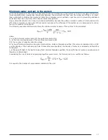
Страница 29: ... reduc tion in the number of transients The following experimental formula allows the minimum water volume of the system to be calculated where Vmin is the minimum water content of the system measured in l Ptot is the total cooling capacity of the machine measured in kW N is the number of capacity reduction steps ΔΤ is the differential allowed on the water temperature Unless otherwise specified th...

Страница 30: ...n order to prevent malfunctioning Once the best position for the unit has been identified you must check that the support slab has the following charac teristics its dimensions must be proportionate to those of the unit if possible longer and wider than the unit by at least 30 cm and 15 20cm higher than the surrounding surface it must be able to bear at least 4 times the operating weight of the un...

Страница 31: ...ween the worst and best situation Particular attention must be given in cases where an environment that is not particularly aggressive becomes aggressive as a consequence of a concomitant cause for example the presence of a flue outlet or an extraction fan We strongly suggest choosing one of the treatment options if at least one of the points listed below is verified there are obvious signs of cor...

Страница 32: ...e obstacles to free air flow you should consider the additional aeraulic head losses that will cause a reduction of the air flow rate and a consequent deterioration of performance The following diagrams show the trend of cooling capacity PC EER total absorbed power Pabs and reduction of the maximum external air temperature in chiller operating mode depending on the aeraulic head losses that the fa...

Страница 33: ...use the unit with EC fans compared to the unit with AC fans working in ideal conditions the output power will be reduced by about 5 the total absorbed power will increase by about 6 5 the EER will be reduced by about 11 5 and the maximum allowed external air temperature for operation at 100 will be reduced by about 2 8K compared to the nominal limit use the unit with oversize EC fans compared to t...

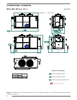
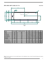
Страница 34: ... 1 1 4 M Uin Uout HYDRAULIC CONFIGURATIONS WITHOUT HYDRAULIC MODULE HYDRAULIC MODULE ST1P ST2P HYDRAULIC MODULE ST1PS ST2PS STS A B C Lh 1488 1337 79 625 5 376 5 2883 FVP UIN A B C FVP 2611 SAP CODE OF OPTIONS 81 Note These drawings are not contractually binding For the installation design refer to the specific dimensional drawing available on request ...

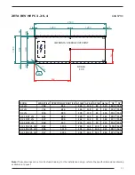
Страница 35: ...118 82 182 924 556 5 2 LN 826 880 278 119 84 196 901 553 3 2 1P 2P_LN 831 889 260 132 92 181 982 556 4 2 1P 2P_LN 837 896 262 132 93 184 977 554 5 2 1P 2P_LN 868 927 276 132 95 197 953 551 3 2 1PS 2PS_LN 882 1105 289 164 130 228 1001 549 4 2 1PS 2PS_LN 886 1110 291 164 130 231 997 547 5 2 1PS 2PS_LN 917 1141 304 164 132 245 973 545 Note These drawings are not contractually binding For the installa...

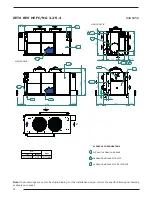
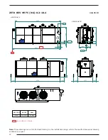
Страница 36: ...4 M G 2 F G 1 1 4 M Uin Uout 167 5 B C Lh 167 5 1221 79 VIEW FROM B Uin A HYDRAULIC CONFIGURATIONS WITHOUT HYDRAULIC MODULE HYDRAULIC MODULE ST1P ST2P HYDRAULIC MODULE ST1PS ST2PS STS A B C 188 1488 Mf 626 376 2587 291 Note These drawings are not contractually binding For the installation design refer to the specific dimensional drawing available on request ...

Страница 37: ... 135 123 222 ZETAREV HE 5 2 FC NG 961 1019 259 137 125 236 ZETAREV HE 3 2 FC NG_1P 2P 961 1023 237 141 137 230 ZETAREV HE 4 2 FC NG_1P 2P 970 1032 238 141 139 234 ZETAREV HE 5 2 FC NG_1P 2P 1002 1065 251 142 141 248 ZETAREV HE 3 2 FC NG_1PS 2PS 1008 1235 268 171 175 275 ZETAREV HE 4 2 FC NG_1PS 2PS 1014 1241 269 171 176 278 ZETAREV HE 5 2 FC NG_1PS 2PS 1049 1277 282 172 179 293 Note These drawings...

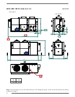
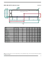
Страница 38: ...B A 250 389 614 1500 1337 1500 168 166 G 2 F G 2 M Uout Uin 1000 209 1788 Uout 180 3549 Uin FVP 1420 FVP 3268 1000 CORM G1 Note These drawings are not contractually binding For the installation design refer to the specific dimensional drawing available on request ...

Страница 39: ...84 1148 217 108 83 166 1369 536 6 2 1PS 2PS_LN 1154 1410 259 148 108 190 1387 552 7 2 1PS 2PS_LN 1168 1424 262 147 109 194 1378 549 6 2 NG_LN 1087 1152 213 101 84 178 1351 519 7 2 NG_LN 1100 1166 215 100 85 183 1343 514 6 2 1P 2P_NG_LN 1131 1204 211 119 98 174 1416 522 7 2 1P 2P_NG_LN 1148 1222 214 118 99 180 1407 517 6 2 1PS 2PS_NG_LN 1217 1482 257 157 124 203 1421 535 7 2 1PS 2PS_NG_LN 1230 1496...

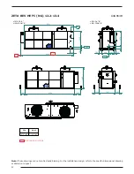
Страница 40: ...A G 2 F G 2 1 2 F G 2 M Uout Uin 8 2 9 2 Uin 10 2 1500 1437 1500 680 423 232 1368 1788 Uout 1000 4354 1000 FVP 4681 FVP SAP CODE OF OPTIONS 4405 Note These drawings are not contractually binding For the installation design refer to the specific dimensional drawing available on request ...

Страница 41: ...551 1842 268 201 194 258 1915 582 9 2 1PS 2PS_LN 1551 1842 268 201 194 258 1915 582 10 2 1PS 2PS_LN 1564 1856 273 202 193 260 1906 585 8 2 NG_LN 1583 1876 276 205 195 262 1910 586 9 2 NG_LN 1443 1520 242 123 133 262 1743 556 10 2 NG_LN 1460 1540 247 124 133 266 1736 557 8 2 1P 2P_NG_LN 1544 1646 241 160 168 254 1889 560 9 2 1P 2P_NG_LN 1559 1664 246 160 168 258 1881 561 10 2 1P 2P_NG_LN 1584 1692 ...

Страница 42: ...OM A A B 680 423 1420 250 232 1500 1500 166 168 1370 180 G 2 1 2F G 2 M Uout Uin Uout 1000 1437 1882 4354 1000 FVP 4681 4391 FVP SAP CODE OF OPTIONS Note These drawings are not contractually binding For the installation design refer to the specific dimensional drawing available on request ...

Страница 43: ... 1750 287 177 157 254 1838 602 12 2 1PS 2PS_LN 1684 1978 304 216 195 274 1879 600 13 2 1PS 2PS_LN 1733 2028 319 220 194 281 1860 606 12 2 NG_LN 1584 1668 260 153 156 265 1826 569 13 2 NG_LN 1630 1716 274 155 155 274 1799 574 12 2 1P 2P_NG_LN 1704 1818 257 198 197 257 1979 573 13 2 1P 2P_NG_LN 1748 1864 271 200 196 265 1951 577 12 2 1PS 2PS_NG_LN 1781 2090 290 238 233 284 1983 578 13 2 1PS 2PS_NG_L...

Страница 44: ...TC_0000_ZRHEFC_EN_Rev01_20161103 ...

Отзывы: