August 1, 2006
8
Lit. No. 27554, Rev. 08
27550
HYDRAULIC UNIT INSTALLATION
Preparing Rams for Installation
1. Remove the plug from the port of one of the angle
rams.
2. Select a 90º elbow, and turn the jam nut as far back
as possible.
3. Lubricate the O-ring with clean hydraulic fluid.
4. Screw the fitting into the angle ram port by hand as far
as it will go. (The washer should be in contact with
both the port face and the shoulder of the jam nut.)
5. Unscrew the fitting to its proper position (no more
than one full turn).
6. Use one wrench to hold the fitting body in position,
and tighten the jam nut with another wrench until
the washer again contacts port face.
Tighten 1/8 to
1/4 turn to lock the fitting in place.
7. Repeat steps 1–6 for the port on the other angle
ram and for both ports on the lift ram. Orient the
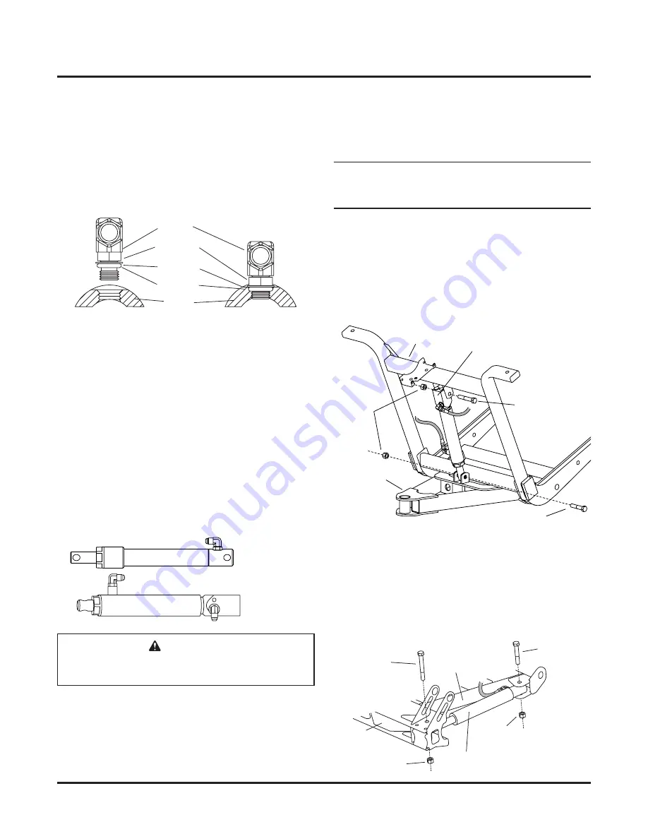
fittings as shown below.
8. Attach 36" HP hoses to the angle rams. Attach the
8" HP hose to the square end of the lift ram, and
attach the 22" HP hose to the other end of the lift
ram. Hand tighten the hoses, then use one wrench
to hold the hose in position and another wrench to
tighten flare nut 1/8 to 1/4 turn beyond hand tight.
Fitting
Jam Nut
Washer
O-Ring
Ram
Attaching Lift and Angle Rams
1. Rotate the plow gear forward until the cross
member contacts the A-frame.
NOTE: Keep the lift ram collapsed as much as
possible until after you attach and tighten all of the
hoses and fill the hydraulic system with fluid.
2. Attach the square end of the lift ram to the plow
gear with a 1/2" x 3" cap screw and a 1/2" locknut.
Attach the other end of the lift ram to the A-frame
with a 1/2" x 2-1/2" cap screw and a 1/2" locknut.
Do not fully tighten the locknuts that secure the
ram; only two or three threads should be showing
past the locknut.
3. With the fittings facing the A-frame, attach each
angle ram to the quadrant with a 1/2" x 4" cap
screw and 1/2" locknut. Use 1/2" x 3" cap screws
and 1/2" locknuts to attach the angle rams to the
A-frame. Do not fully tighten the locknuts that
secure the rams; only two or three threads should
be showing past the locknut.
1/2"
Locknut
A-Frame
1/2" x 3"
Cap Screw
Plow Gear
1/2" x 2-1/2"
Cap Screw
Lift Ram
1/2" Locknut
Quadrant
A-Frame
1/2" x 3"
Cap Screw
Angle Ram
1/2" Locknut
1/2" x 4"
Cap Screw
Lift Ram
Angle Ram
CAUTION
Overtightening the swivel nut will damage the
hydraulic hose.


