


Section VES-R00-20A
030-101639 Rev. B
R
9
0802IARB
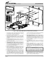
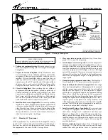
Figure 8.
Close-up of Swing-Arm
External-type
D-ring*
(mounts to
adapter ear)
Internal-arm D-ring
(factory installed)
Route fiber cables
through flexible tube**
(secure tube to wall, if
desired), then route
cable around the
spool**, then through
the D-rings, then on to
the mounted equipment.
Latch
Spool**
* Provided with VESR-00 model only.
** Provided with VESR-14 model only.
Flexible
protective
tube for fiber
cables**
Area for optional
splice tray
Adapter ear
(for 19” equipment)
Sample Fiber
Cable
(not provided)
Bend-radius
protection
boot
SC-type fiber
connector
Affix tube to wall
via a customer-
supplied saddle
and cable-tie
here, if desired.
-
SPLICE TRAY NOTE
-
Located within each arm are threaded holes that accept screws
that can be used to attach a fiber splice tray, if desired.
8.
Perform any equipment testing.
Per company practice, per-
form any equipment testing prior to closing and locking the
SwingRack.
9.
Prepare to close the SwingRack.
Verify all cables are neat,
do not protrude, and are within the confines or walls of the
swing-arms. If the race-way is installed, verify the cover is
installed. If it is not installed, slide or snap it on (do not
pinch any cables). Also verify no equipment, cables, or parts
protrude more than 3.25" past the end of the arms (without
adapter ears), to avoid contact with the top flange of the
back plate when the arms are closed or in the up position.
10.
Close the SwingRack.
After verifying that no cables or
equipment will be pinched, pushed, pressed or pulled out of
position (including the flexible orange tubing), use a hand
on each arm to slowly and carefully lift and close the Swing-
Rack’s arms until the slam-bolt latches are fully-inserted
into the holes provided for them in the back plate’s side
walls. Pull on the arms to verify they are secure.
11.
Install and lock cover, if applicable.
If a cover is provided,
install it at this time. Align and insert the tabs in the bottom
of the cover with and into the slots in the top of the support
plate. Press the top of the cover toward the top flange of the
back plate, insert the provided key into the lock, and turn
the key clockwise to rotate the lock’s tab into the slot pro-
vided for it in back plate’s top flange.
3.5.2
Mounting 19" Equipment
If the equipment to be mounted on the SwingRack was de-
signed for 19" rack mounting, first install the provided adapter
ears onto the ends of each swing-down arm before attaching
the equipment to the arms. Follow the steps below.
1.
Place arms in down position.
Perform Step 1 from Para-
graph 3.5.1 to open the swing-arms.
2.
Attach adapter ears to swing-arms.
Locate the adapter ears
and hardware shipped with the SwingRack. Four ears are
provided. Install one ear in the lowest RU position on each
arm if the equipment is 1 RU high. Install two ears on each
arm if the equipment is 2 RUs high, or if two 1-RU-high
units will be mounted.
Always mount ears and equipment in
the lowest RU position first.
This allows best installer access
and allows the equipment weight to be supported by the
support plate.
3.
Determine proper equipment orientation.
from Paragraph 3.5.1 to properly orient the equipment.
4.
Align mounting holes and attach equipment to ears.
Align
the correct mounting holes of the equipment to be mounted
with the proper, inner-most, holes in the lowest installed
adapter ears (see Figure 8) on the swing-arms. A support
plate helps to temporarily support the equipment during
this process. Attach the equipment (or the equipment’s
mounting ears) to the arms by inserting the provided screws
through the aligned holes and tightening the screws. If two
separate pieces of equipment are being installed, each
1-RU-high, mount the second one at this time in the top RU
position. If a 2-RU-high piece of equipment is mounted, or
a race-way is not provided, skip Step 5 below.
5.
Install external D-rings, if applicable.
Two, external-arm,
3" D-rings are equipped with the VESR-00 model. If de-
sired, these D-rings can be installed at this time (see
Figure 3 or Figure 8 for external D-ring mounting loca-
tions). Attach the D-rings to the
center set of holes
in the
installed adapter ears: first mount the adapter ears to the
swing-arms, then mount the D-rings to the ears using the
provided hardware.
6.
Perform remaining steps.
Paragraph 3.5.1 to install the cable race-way and the bend-
radius fiber cable protection boots, to perform cable


