


Section VES-R00-20A
030-101639 Rev. B
R
8
0802IARB
13.
Attach cover (optional).
If the installed model contains a
cover, attach the cover at this time (model VESR-14 only).
3.5
Mounting Equipment in the SwingRack
Customer-supplied equipment that is either 1 or 2 Rack Units
(RUs) high and designed for either 19" or 23" rack mounting
can be mounted on the SwingRack. If
two
1-RU-high units will
be mounted in the SwingRack, mount the first unit in the bot-
tom or lower position first (when the arms are in the down or
horizontal position). To mount 23" equipment, go to Paragraph
3.5.1. To mount 19" equipment, go to Paragraph 3.5.2
3.5.1
Mounting 23" Equipment in SwingRack
Equipment designed for 23" rack mounting mounts directly to
the ends of the swing-arms of the SwingRack. For 23" mount-
ings, the adapter ears are not needed, unless the race-way
and/or external-arm D-rings are to be installed in one RU.
- RACE-WAY OR D-RING MOUNTING NOTE -
The provided adapter ears serve three purposes: 1) They enable 19" equip-
ment mounting, 2) they enable mounting of the 19" race-way, and 3) they
enable mounting of the external D-rings. If the 23" equipment being
mounted in the SwingRack occupies only 1 RU, then the adapter ears can
be used in the second available RU position for one of the above three
items. If the 23" equipment being mounted in the SwingRack occupies 2
RUs, then the adapter ears, race-way, or D-rings cannot be used.
1.
Place arms in down position.
If the SwingRack’s arms are
in the up (closed) position, maintain contact with the arms
while sliding their latch-release knobs inward to disengage
the latches. Gently place the arms in the down (open or hor-
izontal) position.
2.
Determine proper equipment orientation.
Lift the equip-
ment to be mounted and, per company practice, determine
what orientation it will have when attached to the swing-
arms. Westell recommends that the front panel face the
center of the room, in the arm-down position (or face up,
in the arm-up position). For most equipment, this will place
important options, switches, LEDs, or jacks for testing and
monitoring purposes at the easiest position for installer ac-
cess and viewing.
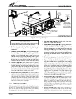
3.
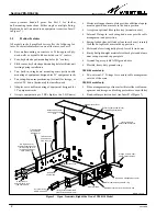
Align mounting holes and attach equipment to SwingRack
arms.
Align the correct mounting holes of the equipment
to be installed with the proper, bottom-most, threaded
holes at the end of each swing-down arm (see Figure 8). A
support plate helps to temporarily support the equipment
during this process. Attach the equipment (or the equip-
ment’s mounting ears) to the arms by inserting the provided
screws through the aligned holes and tightening the screws.
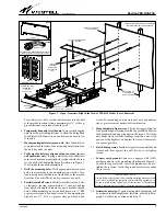
4.
Install external D-rings, if applicable.
Equipped with the
VESR-00 model are two, external-arm, 3" D-rings. If de-
sired, these D-rings can be installed at this time (see
Figure 3 or Figure 8 for the external D-ring mounting loca-
tion). As stated in the NOTE in Paragraph 3.5.1, if
2-RU-high equipment is installed, then the adapter ears
cannot be used to mount the D-rings. However, if space
permits (1 RU is available), attach the D-rings to the
center
set of holes
in the installed adapter ears: first mount the
adapter ears to the swing-arms, then mount the D-rings to
the ears using the provided hardware.
5.
Install race-way (slotted duct), if applicable.
For the
VESR-14 model only, if desired (and if one RU is avail-
able), the provided cable race-way can be installed at this
time in the top RU position, for cable management pur-
poses.
As stated in the NOTE in Paragraph 3.5.1, if the
equipment installed is 2 RUs high, then the race-way cannot
be used, as their mounting holes in the adapter ears are not
available.
Before installing the 19" wide race-way (see
Figure 7), first attach the adapter ears to the top RU posi-
tion at the ends of the swing-arms, using the provided
hardware. Then, to install the race-way, first orient the
race-way so the front cover faces the installer, or the center
of the room. Slide off the front cover. Locate the slots or
mounting holes on the back wall of the race-way (at both
ends) and align the slots with the corresponding inner-most
set of holes in the installed adapter ears, then attach the
race-way to the ears with the provided hardware. If cable
placement and routing will be performed at this time, post-
pone the re-attachment of the race-way’s front cover until
all cable installation and routing is complete.
6.
Install cable boots, if applicable.
The VESR-14 model is
shipped with two bend-radius cable protection boots (see
Inset B of Figure 7). Install the boots near the connector
end of the fiber cable by weaving and gently pressing the
cable into the slot provided in the boot, then slide the boot
up the cable as far as it will go, making it snug up against the
strain-relief of the connector. Repeat for each boot.
- CAUTION -
Always observe proper fiber cable bend radius requirements,
per company practice, and per cable and equipment
manufacturer instructions, to avoid fiber damage.
7.
Perform all cable routing and installer connections.
Tie-
down slots and factory-installed internal-arm D-rings are
provided in the SwingRack for convenient cable routing
and management. Some models also provide a 2-piece fi-
ber-management spool for cable routing or slack purposes,
and a flexible, orange, fiber-cable protection tube at the
back of the arm near the back plate. Fiber cables are typical-
ly routed first through the flexible orange tube, then looped
around the spool in the swing-arm (see Paragraph 2.2.2 if
greater spool slack or storage capacity is desired), routed
through the internal-arm D-rings, brought around the end
of the swing-arm, through any installed external-arm D-
ring and cable race-way, then attached to the appropriate
connector on the mounted equipment. If splicing of fiber
cables is desired at the SwingRack location, use the Westell
splice tray kit (which is mounted inside the swing-arm), per-
form all splicing per company practice, mount the tray in
the arm, and continue with cable routings and connections.
Use all of the aforementioned features to perform all cable
routings, management, connections, fiber splicing, and
cable slack management procedures, per company prac-
tice. Additional D-rings and cables are available (see
Table 3).


