


Section VES-R00-20A
030-101639 Rev. B
R
5
0802IARB
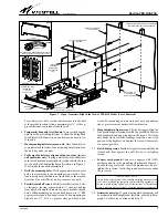
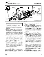
four ears. Always mount ears and equipment to the lowest RU
position first, for best equipment access and support. Each
adapter ear contains 6 holes (3 sets of two holes). When the
ears are positioned as shown in Figure 3, use the outside set of
holes to attach the ears to the end of the swing-arms. The 19"
equipment is then attached to ear’s inside set of holes. Mount-
ing screws are provided. The middle set of holes in each
adapter ear is designed to accept an external 3" D-ring, two of
which are provided with the VESR-00 model, one for each
swing-arm.
2.2
Fiber Management and Protection Features
Additional features are provided on or with the VESR-14 mod-
el to facilitate cable management. These features are described
in Paragraphs 2.2.1 through 2.2.4 below.
2.2.1
Protection Tube
To help protect fiber cables as they enter the arms of the Swing-
Rack, a short length of orange, flexible, fiber-cable protection
tube is factory-installed near the back of the right arm. After
equipment is mounted in the swing-arms, route and dress the
fiber connector cables. When routing cables, start near the low-
er right corner of the back plate, insert the fiber cable into the
free end of the flexible tube, feed it through the tube, then con-
tinue to route the cable through the entire length of the arm’s
inside channel to the end of the arm, using the spool, if desired
(described below), per company practice, and the D-rings. Per
company practice, and if desired, the free end of the flexible
protection tube can be loosely secured to the wall, to restrict ex-
cessive tube movement, with a customer-supplied tie strap and
saddle (see Figure 8).
2.2.2
Fiber Cable Management Spool
A 2-piece fiber cable management spool is factory-installed in-
side and near the back of the right swing-arm. After verifying
how much cable length is needed to reach the appropriate
equipment connectors, wrap any surplus lengths of each fiber
cable around this reel or spool, per company practice. If more
slack management capacity is desired, half of the spool can be
moved to the center of the swing-arm. This is accomplished by
removing the center D-ring, then detaching and moving the
front half of the 2-piece spool to the empty D-ring mounting
holes. In addition, the spool can be detached and moved to the
left or other arm, if desired.
2.2.3
Cable Race-way (Duct)
A protective cable race-way (slotted duct) is provided on the
VESR-14 model only. The race-way mounts to the inner set of
holes in the adapter ears, which are first mounted to the ends
of the swing-arms. The race-way can be used only when the
mounted equipment occupies only 1 RU, leaving the other RU
for the adapter ears and race-way. Numerous top and bottom
slotted holes are provided in the race-way for neat and orga-
nized cable management. After cables are routed through the
swing-arms, remove the cover of the race-way by sliding it off,
place the rear wall of the race-way against the adapter ears,
align the holes, then attach the race-way to the ears with the
provided hardware. Route cables through the race-way to the
slotted hole or tab closest to the equipment’s desired connec-
tor, and press on the race-way slot’s flexible tab to create space
to enable the cable to enter the slotted hole. When all cables are
connected or installed, replace the cover of the race-way by
snapping or pressing it in place, from the race-way’s front side
(or alternately, slide it in from the side).
2.2.4
Bend-Radius Protection Boots
Two, right-angle, bend-radius protection boots (see Inset B of
Figure 7) are provided to help protect fiber cables at their
cable-to-connector strain-relief junction. This junction can be
subject to sharp turns or bends, or frequent bending and twist-
ing during cable routing, installation, and equipment
maintenance and testing procedures. A properly installed boot
also protects the cable from any sharp edges it may contact (in-
cluding ducts or mounted equipment). Each boot provided
contains an open slot along its length that accepts the jacketed
fiber cable. Before mating fiber cable connectors to equipment
connectors, install any protection boots just under the cable’s
connector, per company practice. Gently press the cable into
the boot’s slot, then slide the boot up the cable to the connec-
tor’s strain-relief, as far as it will comfortably but firmly go,
until it is snug.
2.3
Other Features
2.3.1
Locking Cover
A removable but locking cover is provided on the VESR-14
model which both locks the swing-arms in the up position and
restricts hand and visual access to the front of the equipment
mounted in the SwingRack. Place the swing-arms in the up
position. Align the two tabs at the bottom of the locking cover
with the two corresponding slots in the top of the support plate,
then lower or set the cover into place at the front of the Swin-
gRack. Lock the cover with the provided key. To lock or unlock
the cover, insert the key and turn it 1/4-turn to rotate the lock’s
tab either into or out of the slot provided for it in the top flange
of the back plate.
2.3.2
External-Arm 3" D-Rings
On the VESR-00 model, two external-arm 3" D-rings are pro-
vided for additional cable management. These D-rings are
similar in function to the internal-arm D-rings, but mount out-
side the swing-arms, and are only 1 RU tall. These flexible but
sturdy D-rings have a split front edge which can be pressed to
allow ingress and egress of long cables, if desired. These D-
rings mount to the middle set of holes in the adapter ears, as
shown in Figure 8. The D-rings can be used only when 19"
equipment is mounted in the SwingRack, or if any 23" equip-
ment occupies only 1 RU, leaving the other RU for the adapter
ears and D-rings.
3.
INSTALLATION
Installation consists of inspecting the equipment for damages,
following proper safety precautions, gathering the required
tools and equipment, determining the mounting location, and
mounting the SwingRack. The following paragraphs provide de-
tailed instructions for performing these procedures.


