background image

8

ELECTRICAL INFORMATION

AMPERAGE

REQUIRED GAUGE FOR EXTENSION CORDS

25 ft.

50 ft.

100 ft.

150 ft.

15A

14 gauge

12 gauge

No Recommended

No Recommended

IMPORTANT: 

Servicing a double-insulated product requires extreme care and knowledge of the system, and 

should be done only by qualified service personnel using identical replacement parts. Always use original factory 

replacement parts when servicing. 

1. Polarized Plugs.

 To reduce the risk of electric shock, this equipment has a polarized plug (one blade is wider 

than the other). This plug will fit in a polarized outlet only one way. If the plug does not fit fully in the outlet, reverse 

the plug. If it still does not fit, contact a qualified electrician to install a proper outlet. Do not modify the machine 

plug or the extension cord in any way. 

2. Ground fault circuit interrupter protection

 (GFCI) should be provided on the circuit or outlet used for this power 

tool to reduce the risk of electric shock.

3. Service and repair.

 To avoid danger, electrical appliances must only be repaired by a qualified service technician 

using original replacement parts.

GUIDELINES AND RECOMMENDATIONS FOR EXTENSION CORDS

When using an extension cord, be sure to use one heavy enough to carry the current your product will draw. An 

undersized cord will cause a drop in line voltage, resulting in loss of power and overheating. The table below shows 

the correct size to be used according to cord length and ampere rating. When in doubt, use a heavier cord. The 

smaller the gauge number, the heavier the cord. 

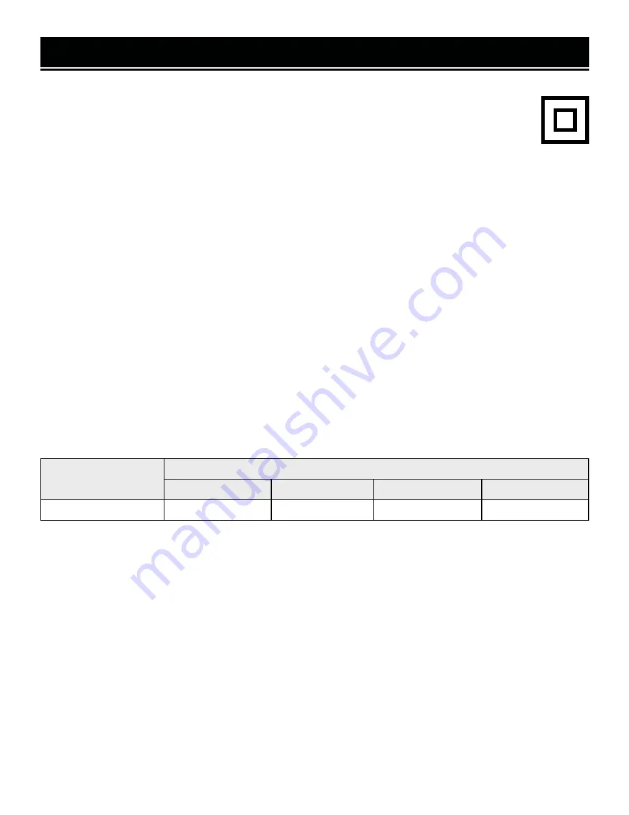
DOUBLE-INSULATED TOOLS

The tool’s electrical system is double-insulated where two systems of insulation are provided. This 

eliminates the need for the usual three-wire grounded power cord. Double-insulated tools do not need 

to be grounded, nor should a means for grounding be added to the product. All exposed metal parts 

are isolated from the internal metal motor components with protecting insulation. 

1. Examine extension cord before use.

 Make sure your extension cord is properly wired and in good condition. 

Always replace a damaged extension cord or have it repaired by a qualified person before using it.

2. Do not abuse extension cord.

 Do not pull on cord to disconnect from receptacle; always disconnect by pulling 

on plug. Disconnect the extension cord from the receptacle before disconnecting the product from the extension 

cord. Protect your extension cords from sharp objects, excessive heat and damp/wet areas.

3. Use a separate electrical circuit for your tool.

 This circuit must not be less than a 12-gauge wire and should 

be protected with a 15A time-delayed fuse. Before connecting the motor to the power line, make sure the switch 

is in the OFF position and the electric current is rated the same as the current stamped on the motor nameplate. 

Running at a lower voltage will damage the motor.

Содержание MM1215

Страница 1: ...ars of rugged trouble free performance Pay close attention to the rules for safe operation warnings and cautions If you use your tool properly and for its intended purpose you will enjoy years of safe reliable service NEED HELP CONTACT US Have product questions Need technical support Please feel free to contact us TECHSUPPORT WENPRODUCTS COM 1 847 429 9263 M F 8AM 5PM CST For replacement parts and...

Страница 2: ...ur Miter Saw 10 Assembly Adjustments 12 19 Operation 19 Maintenance 21 Troubleshooting Guide 23 Exploded View Parts List 25 Warranty Statement 34 OPERATION MAINTENANCE To purchase accessories for your tool visit WENPRODUCTS COM Collapsible Rolling Miter Saw Stand Model MSA330 750 Pound Capacity Miter Saw Stand Model MSA750 MSA750T Multi Purpose Rolling Planer and Miter Saw Tool Stand Model MSA658T...

Страница 3: ... to all users during the entire life of the tool and review it frequently to maximize safety for both yourself and others SPECIFICATIONS SAFETY ALERT SYMBOL Indicates danger warning or caution The safety symbols and the explanations with them deserve your careful attention and understanding Always follow the safety precautions to reduce the risk of fire electric shock or personal injury However pl...

Страница 4: ...c shock PERSONAL SAFETY 1 Stay alert watch what you are doing and use com mon sense when operating a power tool Do not use a power tool while you are tired or under the influence of drugs alcohol or medication A moment of inatten tion while operating power tools may result in serious personal injury 2 Use personal protective equipment Always wear eye protection Protective equipment such as a respi...

Страница 5: ...accordance with these instructions taking into ac count the working conditions and the work to be per formed Use of the power tool for operations different from those intended could result in a hazardous situa tion 8 Use clamps to secure your workpiece to a stable surface Holding a workpiece by hand or using your body to support it may lead to loss of control 9 KEEP GUARDS IN PLACE and in working ...

Страница 6: ... pacemakers could cause pacemaker inter ference or pacemaker failure 4 Wear work gloves when handling saw blades DO NOT wear gloves while operating the saw 5 Sawdust is harmful to your health Use NIOSH ap proved dust masks or other respiratory protection dur ing operation and cleaning 6 Always turn off and unplug the miter saw before mak ing any adjustments or repair tasks Never adjust the miter s...

Страница 7: ... guards are in place Do not operate with any guard disabled dam aged or removed Moving guards must move freely and close instantly 7 Turn on the miter saw and let it reach full speed then slowly slide the saw into the workpiece This will help produce safer and cleaner cuts 8 Always push the saw blade forwards and away from you Do not pull the saw towards you or move the saw backwards while cutting...

Страница 8: ...ting in loss of power and overheating The table below shows the correct size to be used according to cord length and ampere rating When in doubt use a heavier cord The smaller the gauge number the heavier the cord DOUBLE INSULATED TOOLS The tool s electrical system is double insulated where two systems of insulation are provided This eliminates the need for the usual three wire grounded power cord...

Страница 9: ...e saw arm is locked down the miter table is locked in position and the slide lock knob is tightened Only lift the saw by the carrying handles built in to the base of the saw or by the carrying handle located on top of the motor housing Do not lift the saw using the guards or the operating handle UNPACKING TRANSPORTATION WARNING Do not plug in or turn on the tool until it is fully assembled accordi...

Страница 10: ...rred to later in the manual for assembly and operation instructions 1 2 3 5 6 7 8 9 10 11 17 15 14 4 13 12 1 Operating Handle 2 Upper Blade Guard 3 Lower Blade Guard 4 Bevel Scale 5 Right Adjustable Fence 12 Sliding Bar 13 Sliding Bar Lock Knob 14 Workpiece Clamp 15 Left Adjustable Fence 16 Side Carrying Handles 17 Miter Table 6 Base 7 Mounting Hole 8 Table Insert 9 Miter Angle Adjustment Lever 10...

Страница 11: ...9 LED Power Switch 20 Release Bolt 21 Fence Locking Knob 22 Support Bar Locking Knob 23 Workpiece Clamp Holder 24 Workpiece Support Bar 25 Workpiece Clamp Locking Knob 26 Power Switch 27 Top Carry Handle 28 Dust Port 29 Dust Bag 30 Bevel Locking Pin 31 Bevel Locking Knob 24 27 30 ...

Страница 12: ...he blade s rotation arrow points in the same direction as the rotation arrow on the upper blade guard 5 Lower the blade guard making sure that the blade guard is properly lowered and covering the arbor bolt Reinstall the blade guard screw Make sure that the blade guard moves freely and covers the entirety of the blade 6 Allow the lower blade guard to return back into position ASSEMBLY ADJUSTMENTS ...

Страница 13: ...saw will only bevel to the left and has a positive stop at 0 and 33 To move past the 33 positive stop and bevel 45 to the left pull out the bevel pin 3 Tilt the saw arm until the bevel angle indicator points to the desired angle on the bevel scale Fig 3 1 4 To bevel to the right slightly bevel the saw head to the left and pull out the bevel one step With the bevel pin pulled out one step there is ...

Страница 14: ...tments 3 After selecting your miter angle release the miter stop lever and tighten the miter lock knob Fig 4 1 by turning it clockwise to lock the table in place WARNING Be sure the miter table is locked in place before making a cut Failure to do so can cause the table to move during the cut which could result in serious personal in jury INSTALLING THE CLAMP ASSEMBLY The clamp comes pre assembled ...

Страница 15: ...ion bag Fig 7 2 over the dust port Make sure that it is secured in place 3 Open the zipper on the bottom of the bag to empty For efficient operation empty the dust bag when half full to al low for better air flow through the bag 4 If desired use a dust port adapter not included to con nect to a dust extraction system If needed use a hose clamp to tightly clamp the dust hose to the adapter SQUARING...

Страница 16: ...et the bevel angle indicator to 0 Fig 10 1 and tighten the bevel lock knob Fig 2 3 4 Place a combination square not included against the table and alongside the saw blade should be in contact with the surface of the blade not the teeth Wearing work gloves rotate the blade by hand and check the blade to table alignment at several points The edge of the combina tion square and the saw blade should b...

Страница 17: ...counterclockwise To de crease depth turn the depth stop knob clockwise 5 Check that the blade will not hit the table fence kerf board or other part of the saw during the cut Check the cutting depth setting by completing a test cut on a piece of scrap wood Repeat steps 4 5 until the desired depth is achieved ADJUSTING THE FENCE 1 Loosen the fence adjustment knob Fig 12 1 2 Adjust the fence as desir...

Страница 18: ...eft hand threaded Fig 13 3 Re move the washer outer flange and arbor insert Make sure the inner flange stays in place on the arbor 4 Slowly remove the blade by pulling it out and down Clean the arbor bolt washer outer flange and arbor insert ASSEMBLY ADJUSTMENTS 5 Place the arbor insert onto the spindle Place the new blade over the arbor insert IMPORTANT Make sure the blade s rotation arrow points...

Страница 19: ... isn t necessary See section titled Set ting Up Arm Slide on page 12 to disable the sliding func tion For materials with a width over 2 1 2 inches 63 mm the saw arm will need to slide to cut through the workpiece See section titled Setting Up Arm Slide on page 12 to en able the sliding function OPERATION WARNING Do not plug in or turn on the tool until it is fully assembled according to the instru...

Страница 20: ...ece is fully supported against the fence and securely clamped down Check that you have the proper blade for the material you are cutting Without turning on the saw perform a dry run of the cutting operation to check that nothing is obstructing the path of the saw Instructions continue on the next page WARNING Be sure to tighten the miter lock and bevel lock before making a cut Failure to do so cou...

Страница 21: ...orkpiece 5 Unplug the miter saw before leaving your work station Clean your work station and store tools out of reach of chil dren MAINTENANCE WARNING To avoid accidents turn OFF and unplug the tool from the electrical outlet before cleaning adjusting or performing any maintenance work WARNING Any attempt to repair or replace electrical parts on this tool may be hazardous Servicing of the tool mus...

Страница 22: ...o 86 F 4 Cover the miter saw in order to protect it from dust and moisture It is preferable to store it in its original packaging with the instruction manual and all accessories PRODUCT DISPOSAL Used power tools should not be disposed of together with household waste This product contains electronic compo nents that should be recycled Please take this product to your local recycling facility for r...

Страница 23: ...olt is tightened completely 4 Incorrect blade used for workpiece 5 Ensure the blade is compatible with the material type and thickness being cut 6 Blade is installed improperly 6 Ensure blade is installed in correct orientation Excessive noise or vibration 1 Not mounted properly 1 Make sure the saw is mounted securely to a flat and level work surface 2 Blade is damaged 2 Replace blade 3 Blade is n...

Страница 24: ... ordered from wenproducts com 5 Defective motor or other internal problem 5 Stop using the tool and call 1 847 429 9263 for customer service Saw overheats 1 Tool forced to work too fast 1 Do not force the tool Let it work at its own pace Ensure blade selection is appropriate for cut type and workpiece 2 Wrong extension cord gauge 2 Select proper extension cord Refer to Electrical Information on p ...

Страница 25: ...25 EXPLODED VIEW PARTS LIST EXPLODED VIEW PARTS LIST MITER SAW ...

Страница 26: ...MM1215 018 Saw Blade 1 0 19 MM1215 019 Outer Flange 1 No Part No Description Qty 0 20 MM1215 020 Socket Screws M8X16 1 0 21 MM1215 021 Lock Nut M6 1 0 22 MM1215 022 Wave Washer 1 0 23 MM1215 023 Linkage 1 0 24 MM1215 024 Shoulder Screws M5X10 1 0 25 MM1215 025 Screws M6X16 1 0 26 MM1215 026 Socket Screws M5X16 1 0 27 MM1215 027 Shoulder Screws M6X14 1 0 28 MM1215 028 Lock Pin 1 0 29 MM1215 029 C r...

Страница 27: ...27 EXPLODED VIEW PARTS LIST EXPLODED VIEW PARTS LIST MOTOR ASSEMBLY ...

Страница 28: ... MM1215 124 Carbon Brush 2 1 25 MM1215 125 Carbon Brush Holder 2 1 26 MM1215 126 Rating Label 1 No Part No Description Qty 1 27 MM1215 127 Motor Housing 1 1 28 MM1215 128 Warning Label 1 1 29 MM1215 129 Cross head Screws M5X30 2 1 30 MM1215 130 Set Screws M6X10 2 1 31 MM1215 131 Motor End Cap 1 1 32 MM1215 132 Stator 1 1 33 MM1215 133 Self tapping Screws 2 1 34 MM1215 134 Bearing Sleeve 1 1 35 MM1...

Страница 29: ...Rail 2 2 06 MM1215 206 Cross head Screws M4X12 4 2 07 MM1215 207 Liner Bearing Cover 2 2 08 MM1215 208 Filet Washer 4 2 09 MM1215 209 Linear Bearing 3 2 10 MM1215 210 Bearing spacer 1 2 11 MM1215 211 Bevel Arm 1 No Part No Description Qty 2 12 MM1215 212 Washer 1 2 13 MM1215 213 Spring 1 2 14 MM1215 214 Knob M6X30 1 2 15 MM1215 215 Shoulder Screw M6X14 1 2 16 MM1215 216 Wave Washer 1 2 17 MM1215 2...

Страница 30: ...30 EXPLODED VIEW PARTS LIST BASE AND TABLE ASSEMBLY ...

Страница 31: ...Part No Description Qty 3 26 MM1215 326 Label 1 3 27 MM1215 327 Washer 4 3 28 MM1215 328 Knob 2 3 29 MM1215 329 Label 1 3 30 MM1215 330 Base Fence 1 3 31 MM1215 331 Miter Table 1 3 32 MM1215 332 Socket Screw M8X20 1 3 33 MM1215 333 Cross head Screw M5X58 2 3 34 MM1215 334 Washer 2 3 35 MM1215 335 Knob 1 3 36 MM1215 336 Lock plate 1 3 37 MM1215 337 Square Nut M10 1 3 38 MM1215 338 Press plate 1 3 3...

Страница 32: ...dle 1 4 09 MM1215 409 Lock Tab 1 4 10 MM1215 410 Spring 1 4 11 MM1215 411 Clamp Bar 1 4 12 MM1215 412 Clamp Plate 1 4 13 MM1215 413 Support Rod 1 4 14 MM1215 414 Cross head Screw M4X12 1 BLADE GUARD ASSEMBLY No Part No Description Qty 5 01 MM1215 501 Screw M6X16 1 5 02 MM1215 502 Blade Guard Bracket 1 5 03 MM1215 503 Torsion Spring 1 5 04 MM1215 504 Lower Blade Guard 1 5 05 MM1215 505 Washer 2 No ...

Страница 33: ...15 604 End cap 1 BEVEL LOCK HANDLE ASSEMBLY No Part No Description Qty 7 01 MM1215 701 Cross head Screw 1 7 02 MM1215 702 Bevel Lock Knob 1 7 03 MM1215 703 Hex Bolt 1 ARBOR ASSEMBLY No Part No Description Qty 8 01 MM1215 801 C ring 2 8 02 MM1215 802 Gear 1 8 03 MM1215 803 Flat key 1 8 04 MM1215 804 Arbor 1 No Part No Description Qty 8 05 MM1215 805 Cross head Screw 2 8 06 MM1215 806 Bearing 2 8 07...

Страница 34: ...r defective parts and products may need to be sent to WEN before the replacements can be shipped out Upon the confirmation of a WEN representative your product may qualify for repairs and service work When re turning a product for warranty service the shipping charges must be prepaid by the purchaser The product must be shipped in its original container or an equivalent properly packed to withstan...

Страница 35: ...NOTES 35 ...

Страница 36: ...THANKS FOR REMEMBERING V 2022 11 07 ...

Отзывы: