background image

10

10

USING THE GENERATOR FOR THE FIRST TIME

CAUTION: The following section describes the necessary steps to prepare the generator for use.  If after reading 
this section, you are unsure about how to perform any of the steps please call (800) 232-1195 M-F 8-5 CST for 
customer service. Failure to perform these steps properly can damage the generator or shorten its life. 

STEP 1 - ADD OIL

The generator is shipped without oil.  User must add the proper amount of oil before operating the generator for 
the first time.  The oil capacity of the engine crankcase is 20 fl. oz.  For general use (above 40° F), we recommend 
30W, 4-stroke engine oil.  

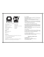
GENERATOR PREPARATION


Oil Dipstick                                       

Fig. 2 - Oil Fill Opening, Dipstick and Oil Level

To add oil, follow these steps

:

1. Make sure the generator is on a level 
surface.  Tilting the generator to assist in 
filling will cause oil to flow into the engine 
areas and will cause damage.  Keep the 
generator level!

2. Remove the dipstick from the engine 
(Fig. 2).

3. Add oil slowly, being careful not to 
overfill the unit. Fill the crank case to the 
upper fill line so the oil lands about halfway 
up the dipstick threads (Fig. 2). 

4. To check the oil level, wipe the dipstick 
with a clean rag. Insert the dipstick into 
the oil fill opening without screwing it in. 
Remove the dipstick to check the oil mark.

5. Slowly add more oil and repeat step 4 

Fig. 1 - Engine Oil Temperature Recommendation

CAUTION

:  Air  cooled  engines  run  hotter  than  automotive 

engines. The use of non-synthetic multi-viscosity oils (5W-30, 
10W-30, etc.) in temperatures above 40° F will result in higher 
than normal oil consumption. When using a multi-viscosity oil, 
check the oil level more frequently than you would otherwise.

ENGINE OIL RECOMMENDATIONS

Select good quality detergent oil bearing the American Petro-
leum Institute (API) service classifications SJ, SL, or SM  (syn-
thetic oils may be used). Use the ASE viscosity grade of oil from 
the following chart (Fig. 1) that matches the starting temperature 
anticipated before the next oil changes.

Oil
Dipstick

Lower Level 
Fill Line

Upper Level 

Fill Line

until the oil mark 
reaches to the top 
of the dipstick (Fig. 
2).  Do not overfill 
the crankcase.  The 
generator is equipped 
with a low-oil sensor 
and will not start 
without a sufficient 
amount of oil.

6. Check for oil leaks 
and firmly tighten the 
dipstick.

Содержание 56352

Страница 1: ...ll supply you years of rugged trouble free performance Pay close attention to the rules for safe operation warnings and cautions If you use your tool properly and for intended purpose you will enjoy y...

Страница 2: ...roduction Safety Information Know Your Generator Assembly Generator Preperation Stopping the Generator Subsequent Starting of the Generator Using the Generator Maintenance Care Storage Transport Speci...

Страница 3: ...the location of the serial number Record generator information in the spaces provided below GENERATOR MODEL NUMBER 56400M DATE OF PURCHASE ______________________________________________ PURCHASED FRO...

Страница 4: ...n this manu al WEN reserves the right to change this product manual and specifications at any time without prior notice Please keep this manual available to all users during the entire life of the gen...

Страница 5: ...apors which can cause severe burns or even death if ignited A nearby open flame can lead to explosion even if it isn t directly in contact with gasoline 5 SAFETY INFORMATION 1 Do not operate near open...

Страница 6: ...after use before touching engine or areas of the generator that be come hot during use 16 Only use generator for its intended purposes 17 Operate only on dry level surfaces 18 Allow generator to run f...

Страница 7: ...6 7 9 10 11 12 14 1 2 3 4 5 6 7 8 Fuel Gauge Fuel Cap 12V Cigarette Lighter Style DC Receptacle Power Indicators 3 total Engine Hour Counter Circuit Reset Buttons 240 120V AC Receptacle Ground Termin...

Страница 8: ...it does NOT have oil and gas in it If it is not dry you will need to do the installation with the generator right side up and on a level surface 1 Unscrew the bolts and remove the washers from your w...

Страница 9: ...d attach the two handles using the 10 13 and the 10 12 mm wrenches Do not tighten the handles too much as this will restrict movement and will prevent the handles from folding up and down as needed 8...

Страница 10: ...pper fill line so the oil lands about halfway up the dipstick threads Fig 2 4 To check the oil level wipe the dipstick with a clean rag Insert the dipstick into the oil fill opening without screwing i...

Страница 11: ...level surface 2 Unscrew fuel cap and set aside NOTE The fuel cap may be tight and hard to unscrew 3 Slowly add unleaded gasoline to the fuel tank Be careful not to overfill The capacity of the fuel ta...

Страница 12: ...breathing CO NEVER use a generator inside homes garages crawl spaces or other partially enclosed areas Deadly levels of carbon monoxide can build up in these areas Using a fan or opening windows and d...

Страница 13: ...mage to the generator 2 Turn the ON OFF switch to the OFF position 3 Turn the fuel valve to the OFF horizontal position CAUTION Allowing gasoline to sit in the fuel tank for long periods of time can m...

Страница 14: ...ank Add additional gasoline as necessary but leave sufficient room in the tank for expansion 14 SUBSEQUENT STARTING OF THE GENERATOR IMPORTANT Use only UNLEADED gasoline Do not use old gasoline Never...

Страница 15: ...ers this extra power requirement Item Rated Running Wattage Surge Wattage 56352 3000 3500 Fig 6 Generator Wattage The total running wattage requirement of the electrical devices connected to the gener...

Страница 16: ...r 800 1300 Computer 800 0 Electric drill 600 900 Television 500 0 Deep freezer 500 500 Garage door opener 480 0 Stereo 400 0 Box fan 300 600 Clock radio 300 0 Security system 180 0 DVD player VCR 100...

Страница 17: ...AUTION Do not connect 50Hz loads to the generator SOME NOTES ABOUT POWER CORDS Long or thin cords can drain the power provided to an electrical device by the generator When using such cords allow for...

Страница 18: ...F 8 5CT CAUTION Never perform maintenance operations while the generator is running Recommended Maintenance Schedule Each 8 hours or daily First 8 hours Every 25 hours Every 3 months or 50 hours Ever...

Страница 19: ...NG THE OIL Check the oil level of the generator according to the Recommended Maintenance Schedule in Fig 9 The genera tor is equipped with an automatic shutoff to protect it from running on low oil Th...

Страница 20: ...a 10 mm hex wrench unscrew the oil drain plug Fig 11 Allow the oil to drain from the engine 3 Reinstall the oil drain plug and tighten with a 10 mm hex wrench TO REFILL THE OIL 1 Make sure the generat...

Страница 21: ...or Occasionally check that the air cleaner is free of excessive dirt Refer to Recom mended Maintenance Schedule in Fig 9 For air cleaner detail refer to Fig 12 1 Unscrew the cover bolt then remove the...

Страница 22: ...ug wrench to gain leverage and loosen the plug 3 Visually inspect the spark plug for cracks or excessive electrode wear Replace as necessary 4 Measure the plug gap with a spark plug gap gauge The gap...

Страница 23: ...a fuel line not included with the generator to the exposed end of the fuel valve 4 Position the fuel line into an appropriate container and open the fuel valve 5 Once the fuel is drained shut off the...

Страница 24: ...transporting generator Tighten fuel cap and vacuum relief valve Drain the fuel tank if possible see Draining the Fuel Tank on page 23 Keep the generator upright Never place the generator side down Do...

Страница 25: ...from triggering Oil is low Add or replace oil Engine runs but there is no electrical output Circuit reset button is off Wait for 2 minutes and push the circuit reset button to the ON position Bad conn...

Страница 26: ...uct 1 Fig 1 8 P54040 Bolt 4 Fig 1 9 P54047 Stud 2 Fig 1 10 P54058 Stud 2 Fig 1 11 P54048 Pin 2 Fig 1 12 P54062 Bolt 4 Fig 1 13 P54060 Spark Plug 1 Fig 1 14 P54054 Cylinder Head Assembly 1 Fig 1 Cylind...

Страница 27: ...1 P54105 Piston Ring Assembly 1 Fig 5 2 P54106 Piston Pin Clip 2 Fig 5 3 P54109 Piston 1 Fig 5 4 P54112 Piston Pin 1 Fig 5 5 P54121 Connecting Rod 1 Fig 5 Piston Ring Connecting Rod No Part Descripti...

Страница 28: ...ting Assembly 1 Fig 12 8 P54619 Bolt 2 Fig 12 Control Assembly No Part Description Qty Fig 9 1 P54718 Carburetor Assembly 1 Fig 9 2 P54168 Air Cleaner Gasket 1 Fig 9 3 P54166 Carburetor Gasket 1 Fig 9...

Страница 29: ...1 Fig 13 10 P54246 Nut 2 Fig 13 Muf er Assembly No Part Description Qty F14 1 P54371 Fuel Tank 1 F14 2 P54386 Cushion 4 F14 3 P54396 Fitting Bush 4 F14 4 P54384 Washer 4 F14 5 P54186 Bolt 4 F14 6 P543...

Страница 30: ...62 Grounding Terminal 1 Fig 16 8 P54838 Circuit Breaker 2 Fig 16 9 P54272 120 240V Receptacle 1 Fig 16 11 56352 1611 Wiring Harness 1 Fig 16 12 56352 1612 Rear Panel 1 Fig 16 13 P54304 Bolt 4 Fig 16 1...

Страница 31: ...Bolt 2 Fig 19 3 P54876 3 Nut 2 Fig 19 4 P54876 3 Steel Handle 2 Fig 19 5 P54876 5 Rubber Handle Sleeves 2 Fig 19 Handles No Part Description Qty Fig 18 1 P54872 1 Wheel 2 Fig 18 2 P54879 Wheel Shaft 2...

Страница 32: ...32 WIRING DIAGRAM...

Страница 33: ...f Great Lakes Technologies LLC Third party vendors such as garage sales pawn shops resale shops or any other secondhand merchant void the warranty included with this product Contact techsupport wenpro...

Страница 34: ...THANKS FOR REMEMBERING...

Отзывы: