background image


Basic Installation and Configuration Guidelines  

Use minimum 6AWG copper conductors only. 
Torque fi eld connections between 21 and 23 in lbs. 
Readily accessible disconnecting means to be provided at time of installation. 
Permanently connected power supply. 
Connect  only  to  a  circuit  protected  by  a  Class  A  Ground  Fault  Circuit  Interrupter  (GFCI)  or  Residual 
Current Device (RCD) mounted at least 5’ (1.52M) from the inside walls of the spa/hot tub and in line of 
sight from the equipment compartment. 
CSA enclosure: Type 2 
Refer to Wiring Diagram inside the cover of the control enclosure. 
Refer to Installation and Safety Instructions provided by the spa manufacturer. 
 
Warning: People with infectious diseases should not use a spa or hot tub. 
Warning: To avoid injury, exercise care when entering or exiting the spa or hot tub. 
Warning: Do not use a spa or hot tub immediately following strenuous exercise. 
Warning: Prolonged immersion in a spa or hot tub may be injurious to your health. 
Warning: Maintain water chemistry in accordance with the Manufacturers instructions. 
Warning: The equipment and controls shall be located not less than 1.5 meters horizontally from the spa 
or hot tub. 

Warning! GFCI or RCD Protection. 

The Owner should test and reset the GFCI or RCD on a regular basis to verify its function. 
 

Warning! Shock Hazard!  

No User Serviceable Parts. 

Do not attempt service of this control system. Contact your dealer or service organization for assistance. 
Follow  all  owner’s  manual  power  connection  instructions.  Installation  must  be  performed  by  a  licensed 
electrician and all grounding connections must be properly installed. 


CSA Compliance 

Caution: 

•  Test the ground fault circuit interrupter before each use of the spa. 
•  Read the instruction manual. 
•  Adequate drainage must be provided if the equipment is to be installed in a pit. 
•  For use only within an enclosure rated CSA Enclosure 3. 
•    Connect  only  to  a  circuit  protected  by  a  Class  A  ground  fault  circuit  interrupter  or  residual  current 
device. 
•    To  ensure  continued  protection  against  shock  hazard,  use  only  identical  replacement  parts  when 
servicing. 
•  Install a suitably rated suction guard to match the maximum fl ow rate marked. 
 

Warning: 

•  Water temperature in excess of 38°C may be injurious to your health. 
•  Disconnect the electrical power before servicing. 
 

Warning 

•  Disconnect the electric power before servicing. Keep access door closed. 


Содержание TRIGLAV

Страница 1: ...USER MANUAL TRIGLAV SPA SYSTEM www wellis eu Version 01 2014 1x3HP Hydromassage pumps New GS100 VL260 control system 28 jets Chromotherapy lamp with 55 LEDs UV C water sanitizer WPC frame...

Страница 2: ...imum Total number of jets 28 pc Hydromassage pump 1x 3 HP 230V 50Hz Hot air blower pump Energy efficient LAING circulation pump Diverter 1pc Chromotherapy lighting 1 lamp with 55 LEDs Exclusive colour...

Страница 3: ...rranted against cracking blistering or delaminat ing due to defects in materials or workmanship for three years from the original date of delivery 2 years on spa plumbing Spa fittings and plumbing are...

Страница 4: ...for one year from the original date of delivery 2 year on ISIS Genesis disinfection system The factory installed ISIS Genesis disinfection systems are warranted against failure due to defects in mater...

Страница 5: ...liability or any other legal theory related to this product All consequential expenses including loss of use damages or contingent liabilities arising out of any alleged deficiencies of the spa are sp...

Страница 6: ...ns misuses abuses or if any repairs are attempted by anyone other than its authorised dealers 6 If damage to the spa has resulted from improper use of thermo cover 7 If damage to the spa has resulted...

Страница 7: ...orsz g Kft be liable for costs associated with but not limited to building alterations or finishes and under no circumstances will be liable for greater expense than the amount paid for the product TH...

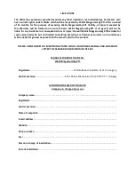
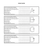
Страница 8: ...iled component _____________________________ New deadline for the warranty _____________________________ The announcement date of damage _____________________________ Date of received goods parts for...

Страница 9: ......

Страница 10: ......

Страница 11: ......

Страница 12: ......

Страница 13: ...away form rain snow if possible build a gazebo for your spa 1 Don t attempt to open the electrical control box There are no user serviceable parts inside 2 Drain clean and refill your spa with fresh w...

Страница 14: ...water Microorganisms are small microscopic organisms which cannot be detected with the naked eye and are continuously getting into the water through rain wind and the body of the bathers If they are...

Страница 15: ...TROUBLESHOOTING...

Страница 16: ......

Страница 17: ...ruction Manual for complete instructions on Power up and Pump Priming The Priming mode will last for less than 5 minutes press Temp or Set to skip Priming Mode and then the spa will begin to heat the...

Страница 18: ...il next power up After the pump has been running for 2 minutes the temperature will be displayed DO NOT ENTER THE WATER Remove the spa cover and allow water to cool Once the heater has cooled reset by...

Страница 19: ...trols shall be located not less than 1 5 meters horizontally from the spa or hot tub Warning GFCI or RCD Protection The Owner should test and reset the GFCI or RCD on a regular basis to verify its fun...

Страница 20: ...of the inspection pit The inspection pit has to be aired accordingly proposal building in an extractor fan The inspection pit s minimum width is 60 cm around the spa If the spa is placed indoor please...

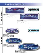
Страница 21: ...Group System PN 56300 System Model MP7 GS100 DCA 3 0K Software Version 41 EPN 3825 Base PCBA PN 56301 PCB VS100C PN 24084 Rev A Base Panels VL200 Mini PN 55123 VL240 MVP240 PN 55080 VL260 MVP260 PN 55...

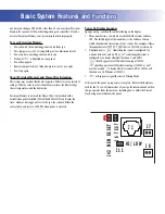
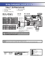
Страница 22: ...nimum 32A optimum 50Hz 3 wires line neutral ground System Outputs Basic System Features and Functions Basic System Features and Functions Setup 1 As Manufactured 230V Pump 1 2 Speed 230V Ozone 10V Spa...

Страница 23: ...that is a VS511SZ at version 38 Displayed next is indicating the system is configured for a heater between 3 and 6 kW or indicating the system is configured for a heater effectively between 1 and 3 k...

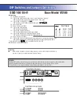
Страница 24: ...S NORMALLY OFF ALL UNUSED SWITCHES SHOULD BE OFF TEST MODE OFF UNUSED P1 TEMP LIGHT DUPLEX PANEL N A MUST BE OFF SEE PUMP TABLE 60HZ OPERATION STD ECON SLEEP ALLOWED DEGREES FAHRENHEIT SEE PUMP TABLE...

Страница 25: ...OFF A2 ON position Button layout will be Pump 1 Light Temp Down Temp Up OFF position Button layout will be Unused Pump 1 Temp Light A3 ON position use Mini Panel OFF position use Lite Duplex or Digit...

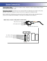
Страница 26: ...nector Voltage The VS100 circuit board is factory configured to deliver a preset voltage of 120V to the on board ozone connector J29 Balboa Ozone Generator The board is set up to operate a 120V ozone...

Страница 27: ...erlay PN 11746 Connects to Main Panel terminal J1 DIP switch A3 must be OFF DIP switch A3 must be ON VL401 Lite Digital PN 54665 with Overlay PN 11885 Connects to Main Panel terminal J1 Jets Light War...

Отзывы: