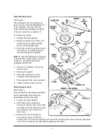
background image

6

Guard Replacement

See Figure 1.
After extended use, the guard may
become worn and need adjustment or
to be replaced. Or if you drop the
angle grinder and damage the guard,
it may be necessary to replace it.

To replace the guard:
1. Unplug the angle grinder.
2. Depress spindle lock button and

rotate clamp nut with provided
wrench until spindle locks.

3. Using the wrench provided, loosen

and remove nut, grinding wheel
and disc flange from spindle.

Note:

To prevent damage to the spindle

or spindle lock, always allow motor to
come to a complete stop before
engaging spindle lock.

4. Using a screwdriver, loosen the

clamp screw.

5. Remove the guard.
6. Place the new guard on the 

shoulder of the bearing cap.

7. Rotate guard to the correct position.
8. Tighten clamp screw securely.

Brush Replacement

See Figure 2.
This product has externally accessible
brush assemblies that should be 
periodically checked for wear.
1. Unplug the angle grinder.
2. With a flat head screwdriver,

remove the brush caps. The brush
assembly is spring loaded and will
pop out when you remove the
brush cap.

3. Remove the brush assembly

(brush and spring). Check the
brushes first. You need to replace the brush if the length of the carbon remains less than
1/4in. Do not replace one side without replacing the other.


Содержание 1433781

Страница 1: ...gle Ginder Set OWNER S MANUAL Item 1433781 WARNING Read carefully and understand all INSTRUCTIONS before operating Failure to follow the safety rules and other basic safety precautions may result in s...

Страница 2: ...______ Save the receipt warranty and these instructions It is important that you read the entire manual to become familiar with this product before you begin using it This machine is designed for cert...

Страница 3: ...Using power tools in confined work areas may put you dangerously close to cutting tools and rotating parts ELECTRICAL SAFETY WARNING Always check to ensure the power supply corresponds to the voltage...

Страница 4: ...ension cord and power receptacle PERSONAL SAFETY Stay alert watch what you are doing and use common sense when operating a power tool Do not use a power tool while you are tired or under the influence...

Страница 5: ...y to force the tool If rotational speed drops abnormally the pressure should be released immediately Little more than the weight of the tool should be applied Forcing and excessive pressure can cause...

Страница 6: ...otective clothing described herein and follow all safety instructions also described herein Do not use any kind of attachment discs or otherwise that has a diameter of greater than 4 1 2 in Remove the...

Страница 7: ...lete stop before engaging spindle lock 4 Using a screwdriver loosen the clamp screw 5 Remove the guard 6 Place the new guard on the shoulder of the bearing cap 7 Rotate guard to the correct position 8...

Страница 8: ...tely and have the problem corrected before further use Have necessary repairs made by qualified service personnel Keep cutting tools sharp and clean Properly maintained cutting tools with sharp cuttin...

Страница 9: ...ir slowly Motor is overloaded by Reduce force applied to tool unnecessary force Armature has shorted Service agent repair sections Motor runs but disc will Gear shaft or woodruff key Service agent rep...

Страница 10: ...Oil impergnated bearings 1 19 Lock pin 1 20 Pin spring 1 21 Screw ST4 2X20 4 22 Pin cap 1 23 Gear case 1 25 Pinion 1 26 Ball bearing 608 2Z 1 27 O ring 1 No Description Qty 29 Armature 1 30 Ball beari...

Страница 11: ...1 2 3 4 6 7 9 10 11 12 13 14 15 16 18 17 19 20 22 23 25 26 27 29 30 31 32 33 34 35 36 37 54 44 45 46 21 8 8 5 55 38 43 49 48 40 49 50 51 52 53...

Страница 12: ...re lead from lead based paints crystalline silica from bricks and cement and other masonry products and arsenic and chromium from chemically treated lumber Your risk from these exposures varies depend...

Отзывы: