


A
QUA
L
OGIC
COMPANION
WATER
HEATER
—
Product Manual
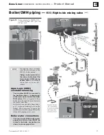
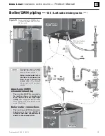
Boiler/CWH piping —
155 / Left-side mixing valve
CONNECTIONS TO BOILER
AND SYSTEM
4HE!QUA,OGIC#7( CANBEPLACEDWITHITS
$(7CONNECTIONSONTHELEFTSIDEORONTHE
RIGHTSIDEBYROTATINGTHEUNITDEGREES
4HIS INSTRUCTION IS FOR INSTALLATIONS WITH THE
#(7WITHITS$(7CONNECTIONSONTHE,%&4
SIDE4HE BOILER SHOWN MUST BE A MODEL
7-
"OILERWATER2%452.CONNECTIONFROM!QUA
,OGIC#7(
"OILERWATER3500,9CONNECTIONTO!QUA,OGIC
#7(
7ATERHEATER40RELIEFVALVECONNECTION
T&P relief valve is shipped loose with the Aqua Logic (CWH)
for field installation.
5PPERTANKTEMPERATURESENSOR
$(7SUPPLYANDRETURNCONNECTIONSONSIDE
Follow instructions on page 7 to install the mixing valve that
is supplied with the Aqua Logic (CWH).
"OILERHOTWATER3500,9TO!QUA,OGIC#7(
"OILERWATER2%452.FROM!QUA,OGIC#7(
'ASSUPPLYCONNECTIONTOBOILER
Installer must provide hard piping or flexible gas line between
boiler connection and gas line connection (item 20).
#ONDENSATETRAPCONNECTIONTOBOILER
!QUA,OGIC#7( BOILERWATERCIRCULATOR
SHIPPEDLOOSEWITH!QUA,OGIC#7(
This circulator is shipped loose with the Aqua Logic (CWH).
The circulator flows boiler water through the internal heat
exchanger coil. The WM97+ boiler control cycles the circula-
tor based on domestic water demand.
The circulator must be installed in the location and flow di-
rection shown on the next page. Otherwise, the water heater
will not perform correctly.
The circulator is 3-speed with an integral flow/check valve.
The circulator speed MUST be set at “1(LO)” when
connected to a WM97+70 or 110. The circulator
speed MUST be set at “3(HI)” when connected to
a WM97+155.
#IRCULATORMOUNTINGHARDWARE
SHIPPEDLOOSEWITH
!QUA,OGIC#7(
The lower mounting flange, bolts, nuts and gaskets are
shipped loose for installation with the circulator.
5PPERCIRCULATORmANGEBOILERWATERCONNECTION
SHIPPEDLOOSEWITH!QUA,OGIC#7(
This fitting is shipped loose for field installation in the loca-
tion and position shown on the opposite page.
&LEXIBLEBOILERWATER2%452.LINE
EITHEROFTWO
mEXIBLELINESSHIPPEDLOOSEWITHTHE!QUA,OGIC#7(
Two 1-inch flexible stainless steel hoses are shipped loose for
field installation. Use one hose each for boiler water Aqua
Logic (CWH) supply and return connections. Make sure a
gasket is placed in each the hex fittings on the hose ends. No
pipe dope or tape is needed. DO NOT over-tighten — gasket
would be damaged.
3ERVICETEEv
SHIPPEDLOOSEWITH!QUA,OGIC#7(
Install the service tee in the location shown in this manual
to provide location for the boiler drain valve (item 16). A
bushing, 1”x¾” NPT, is supplied for mounting the boiler
drain valve as shown in this manual.
"USHINGFORMOUNTINGHOSEBIBBDRAINVALVE
SHIPPEDLOOSEWITH!QUA,OGIC#7(
Install the 1” x ¾” bushing in the service tee.
"OILERDRAINVALVEÐv
SHIPPEDLOOSEWITHBOILER
This valve is shipped loose with the WM97+ boiler. It must
be located as shown on the opposite page when the boiler is
connected to a Aqua Logic (CWH).
&LEXIBLEBOILERWATER3500,9LINE
EITHEROFTWO
mEXIBLELINESSHIPPEDLOOSEWITHTHE!QUA,OGIC#7(
Two 1-inch flexible stainless steel hoses are shipped loose for
field installation. Use one hose each for boiler water Aqua
Logic (CWH) supply and return connections. Make sure a
gasket is placed in each the hex fittings on the hose ends. No
pipe dope or tape is needed. DO NOT over-tighten — gasket
would be damaged.
40RELIEFVALVE
SHIPPEDLOOSEWITH!QUA,OGIC#7(
T & P relief valve is shipped loose with the Aqua Logic (CWH)
for field installation in the location shown on the next page.
2ELIEFVALVEDISCHARGEPIPING
The relief valve outlet MUST be piped to a safe discharge
location, following all local codes. See page 9 for instructions
and requirements.
'ASCONNECTIONWITHMANUALGASVALVEUNION
ANDDRIPLEG
GASVALVEISSHIPPEDLOOSEWITHBOILER
The manual gas valve shown on the opposite page is shipped
loose for field installation. Follow all instructions in the
WM97+ Boiler manual for sizing and installing gas connec-
tions. The manual gas valve and piping shown as item 20 must
be installed OUTSIDE the piping access panel and braced/
supported from the wall or other structure. Orient the piping
for best routing through one of the piping access panel sides.
4OBUILDINGGASSUPPLY
#ONDENSATETRAPASSEMBLY
SHIPPEDLOOSEWITHBOILER
The trap assembly is shipped loose for field assembly and
installation. Follow WM97+boiler manual instructions for
trap assembly and installation. Orient the trap for best routing
of the condensate drain line through the right or left opening
in the piping access cover.
#ONNECTTOCONDENSATEDRAINPIPING
Follow all WM97+ Boiler manual instructions for connecting
condensate drain piping.
Part number 635-500-156/1113
18