background image

www.weg.net


WECM / Emerald eZA Manual | 5 

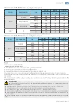
Allowed loads for WECM (IEC 80) motors, according maximum speed:

Direction

Mounting position

Type

1500 rpm

1800 rpm

3000 rpm

Force (kN)

Force (kN)

Force (kN)

Axial 

1)

Horizontal

Pushing 

0.90

0.86

0.74

Pulling 

0.50

0.46

0.34

Vertical shaft down

Pushing 

0.96

0,91

0.77

Pulling 

0.47

0.44

0.33

Vertical shaft up

Pushing 

0.87

0.84

0.73

Pulling 

0.56

0.51

0.37

Radial 

2)

All

L

0.66

0.61

0.49

L/2

0.74

0.69

0.56

Table 1 - Maximum permissible thrust - Fr in (kN) 20000 hours

Allowed loads for WECM (IEC 100) motors, according maximum speed:

Direction

Mounting position

Type

1500 rpm

1800 rpm

3000 rpm

Force (kN)

Force (kN)

Force (kN)

Axial 

1)

Horizontal

Pushing

1.31

1.25

1.10

Pulling

0.71

0.65

0.50

Vertical shaft down

Pushing

1.46

1.37

1.18

Pulling

0.62

0.58

0.45

Vertical shaft up

Pushing

1.22

1.18

1.05

Pulling

0.86

0.76

0.58

Radial 

2)

All

L

0.96

0.88

0.74

L/2

1.07

1.0

0.85

Table 2 - Maximum permissible thrust - Fr in (kN) 20000 hours

Notes:

1)

 Axial maximum load (radial zero).

2)

 Radial maximum load (axial zero).

1 - All belt loads are considered to act in vertically downward direction.  
2 - Overhung loads include belt tension and weight of sheave.
3 - Overhung load limits do not include any effect of unbalanced magnetic pull.
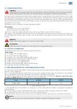
Only remove the corrosion protection grease from the shaft end and flange immediately before the motor installation.
Unless specified otherwise in the purchase order, WEG motors are dynamically balanced with “half key” and without load 
(uncoupled).
The driving elements, such as pulleys, couplings, etc., must be balanced with “half key” before they are mounted on the 
shaft of the motors.

ATTENTION!

g   

The air used for cooling the motor must be at ambient temperature, limited to the temperature indicated on 

the motor nameplate;


Take the required measures in order to ensure the degree of protection indicated on the motor nameplate:


Unused cable inlet holes in the terminal boxes must be properly closed with blanking plugs;


The cable entries used must be fitted with components, such as, cable glands and conduits;


Components supplied loose (for example, terminal boxes mounted separately) must be properly closed and sealed;


Fixing elements mounted in the threaded through holes in the motor enclosure (for example, the flange) must be 

properly sealed.


For flying leads motors, do not push the overlength of leads into the motor in order to prevent that they touch the 

rotor.

Содержание WECM

Страница 1: ...www weg net WECM Emerald eZA Manual 1 WECM Emerald eZA Three Phase Motors Installation Operation and Maintenance Manual Motors Automation Energy Transmission Distribution Coatings...
Страница 2: ...e we advise to make a careful and detailed study of the instructions contained herein before performing any procedures on the motor The noncompliance with the instructions informed in this manual and...

Страница 3: ...roduct as it may interfere with the proper operation of the device ATTENTION Any service on the internal parts of the motor must be performed by qualified personnel only since due to the attraction be...

Страница 4: ...erformed according to the applicable standards and that the shaft key has been securely fastened before the motor is started When available do not lift and or carry the product holding by the input ca...

Страница 5: ...verhung loads include belt tension and weight of sheave 3 Overhung load limits do not include any effect of unbalanced magnetic pull Only remove the corrosion protection grease from the shaft end and...

Страница 6: ...IP66 the drain plugs must remain at closed position being opened only during the motor maintenance procedures Slinger WECM Emerald product in vertical shaft up mounting should be fitted with water sl...

Страница 7: ...solid grounded neutral 5 2 CONTROL CONNECTIONS Make the control connections following nameplate indication Three phase DC voltage VDC and GND terminals DC current ADC and GND terminals Frequency duty...

Страница 8: ...o select between local or remote speed adjust Remove the lid from the back side of the drive cover Use the DIP switch identified as L R to select between local L or remote R Reinstall the lid to the b...

Страница 9: ...agea Lower than 2 VDC Zero motor is off From 2 to 10 VDC Maxb Minc 8 ISd 2 Min DC current Lower than 4 mA DC Zero motor is off From 4 to 20 mA DC Maxb Minc 16 ISd 4 Min Frequency Lower than 10 Zero mo...

Страница 10: ...value for the remote speed adjust signals can be changed Using the optional WEG EC Motor Speed Controller see item 6 5 Using the product local tact buttons only up to the maximum speed set by WEG EC M...

Страница 11: ...the back side of drive cover after the connections are done Maximum speed adjust Remove the lid from the back side of the drive cover Connect the external controller to the EC motor using the cable su...

Страница 12: ...regime considering the critical and special use of this function NOTE When the user activates the Fire Mode function he she acknowledges that the protection functions of the WECM Emerald eZA are disab...

Страница 13: ...g Figure 11 Modbus connecting After completing the above preparations please turn on the power of the ECM Motor Confirm the ECM Motor Modbus slaver address The default address is 0x55 85 2 Operation i...

Страница 14: ...and click write Figure 15 Step 3 After write in the new address the old one is disable Input the new address in Node and check communication Figure 16 Figure 15 Write address Figure 16 Check communic...

Страница 15: ...different serial configuration The serial parameters of inverter can be changed by Modbus command The register 0x0008 is used to set the baud rate writing the corresponding baud rate in the register 0...

Страница 16: ...00 08 00 03 06 96 00 00 02 00 01 D4 88 10 The slaver responses format R 13 33 31 114 55 10 00 08 00 03 0C 1E When slaver responses it means setting successfully 9 Modbus command and address 01 Request...

Страница 17: ...troller Read Register address 0x0002 R 03 FCT Max Speed Read Register address 0x0003 R 03 Current Max Speed Read Register address 0x0004 R 03 Read motor Target speed Read Register address 0x0005 R 03...

Страница 18: ...ss 0000 Table 9 Register table 11 Fault error code Error Code Fault Description 0x0001 DCBUS LOW 0x0002 DCBUS HIGH 0x0003 OVER CURRENT HARDWARE PROTECTION 0x0004 TEMPERATURE CRITICALLY HIGH 0x0005 LOC...

Страница 19: ...s Motor model Batch number and manufacturing date available in the motor nameplate refer to item 4 Installed software version available in the drive label refer to item 4 8 MAINTENANCE DANGER g Before...

Страница 20: ...hnical documents especially those set out in the product Installation Operation and Maintenance Manual as well as the applicable standards and regulations in force in each country Defects arising from...

Страница 21: ...position IM code EN 60034 8 2007 A1 2014 Rotating electrical machines Part 8 Terminal markings and direction of rotation EN 60034 9 2005 A1 2007 Rotating electrical machines Part 9 Noise limits EN 60...

Страница 22: ...en installed maintained and used in applications for which they were designed and in compliance with the relevant installation standards and manufacturer s instructions comply with the provisions of t...

Страница 23: ...ey were designed and in compliance with the relevant installation standards and manufacturer s instructions comply with the provisions of the following relevant United Kingdom statutory requirements w...

Страница 24: ...6 4000 motores weg net www weg net The values shown are subject to change without prior notice The information contained is reference values Cod 50119773 Rev 00 Date m a 05 2022 MOTORS For WEG s world...

Отзывы: