11371757 Installation, operation and maintenance manual – Squirrel cage motor – M line – Vertical
l 31
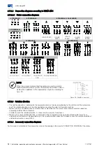
Figure 4.11: Angular alignment
Figure 4.11 shows the angular misalignment and a
practical form to measure it.
The measurement is done in four points 90° away from
each other, with the two half-couplings rotating together
in order to eliminate effects of support surface
irregularities on the dial gauge tip. Choosing the upper
vertical point as 0°, half of the difference between the dial
gauge measurements at the 0° and 180° points
represents the vertical misalignment. In case of deviation,
it must be corrected by adding or removing alignment
shims.
Half the difference between the dial gauge measurements
at the 90° and 270° points represents the horizontal
misalignment, which must be properly corrected by
displacing the motor in the lateral/angular direction.
Half of the maximum difference among the dial gauge
measurements in a complete rotation represents the
maximum angular misalignment found.
The misalignment in a complete shaft rotation, with rigid
or semi flexible coupling, cannot exceed 0.03 mm.
When flexible couplings are used, greater values than
those indicated above are acceptable, provided that they
do not exceed the value allowed by the coupling
manufacturer.
It is recommended to keep a safety margin for these
values.
In the alignment/leveling, the influence of the
temperature on the motor and the driven machine must
be taken into account. Different expansions of the parts
may change the alignment/leveling conditions during
operation.
4.8.8
Hollow shaft motor alignment
Motors with hollow shaft require an exact alignment of
the motor shaft with the driven machine shaft. The pump
shaft works as a pendulum supported by the upper
coupling and the motor bearing.
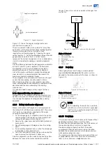
1.
Fix the dial gauge by its magnetic base to the pump
shaft and align it with the base surface (motor shaft),
setting the dial gauge to zero (Figure 4.12);
2.
Remove the upper cover and rotate both motor and
pump shafts;
3.
Read the dial gauge at 90 degrees from the starting
point;
4.
An acceptable alignment occurs when the dial gauge
reading does not exceed 0.05 mm;
5.
Use shims between the motor flange surface and the
base to correct the alignment, if necessary.
Small misalignments can be corrected by inserting shims
between the faces of the motor and driven machine
flanges. These shims can also compensate flanges that
are not flat.
Figure 4.12: Alignment of motors with hollow shaft
Figure 4.12 legend:
1.
Upper bearing
2.
Lower guide bearing
3.
Dial gauge
4.
Motor hollow shaft
5.
Flange
6.
Pump shaft
4.8.9
Doweling
After aligning the set and having assured a perfect
alignment
(both, hot and cold)
, the motor must be
doweled to the anchor plate or to the base, as shown in
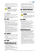
Figure 4.13.
Figure 4.13: Dowel pin set
Figure 4.13 legend:
1.
Dowel pin (optional supply)
2.
Nut (optional supply)
3.
Washer (optional supply)
NOTE
For the doweling, the motor has a pre-hole
with Ø9 mm, which must be first expanded
to Ø11.5 mm, and then reamed to Ø12 mm
with a taper of 1:50.
4.8.10
Couplings
Only proper couplings, which convey only torque without
generating transversal forces, must be used.
For both flexible and rigid couplings, the shaft centers of
the coupled machines must be in a single line.
Flexible couplings mitigate the effects of residual
misalignments and prevent transmission of vibration
between the coupled machines, which does not occur
when rigid couplings are used.
The coupling must be mounted or removed with the aid
of proper devices and never by means of rudimentary
tools, such as hammers, sledgehammers, etc.
Angular misalignment
1
2
3
4
5
6
Axial measurement
Содержание M line Series
Страница 2: ......
Страница 4: ......
Страница 6: ......
Страница 58: ...www weg net 58 l Installation operation and maintenance manual Squirrel cage motor M line Vertical 11371757...


