


CFW501 | 33
Troubleshooting and Maintenance
E
ng
lis
h
6 TROUBLESHOOTING AND MAINTENANCE
6.1 FAULT AND ALARMS
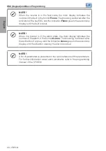
NOTE!
Refer to the quick reference and to the programming manual of the
CFW501 for further information about each fault or alarm.
6.2 SOLUTIONS FOR THE MOST FREQUENT PROBLEMS
Table 6.1:
Solutions for the Most Frequent Problems
Problem
Point to be Verified
Corrective Action
Motor will not
start
Incorrect wiring
1. Check all the power and command connections.
Analog reference
(if used)
1. Check if the external signal is properly connected.
2. Check the status of the control potentiometer (if used).
Wrong settings
1. Check if the parameters values are correct for the
application.
Fault
1. Check if the inverter is disabled due to a fault condition.
Motor stall
1. Decrease the motor overload.
2. Increase P0136, P0137 (V/F).
Motor speed
oscillates
Loose connections
1. Stop the inverter, turn off the power supply and tighten all
the connections.
2. Check all the internal connections of the inverter.
Defective speed
reference
potentiometer
1. Replace the potentiometer.
Oscillation of the
external analog
reference
1. Identify the cause of the oscillation. If the cause is electrical
noise, use shielded cables or separate them from the
power or command wiring.
2. Interconnect the GND of the analog reference to the
grounding connection of the inverter.
Too high or too
low motor speed
Incorrect settings
(reference limits)
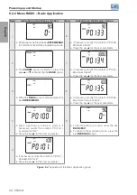
1. Check whether the content of P0133 (minimum speed) and
P0134 (maximum speed) are properly set for the motor and
application used.
Control signal of the
analog reference
(if used)
1. Check the level of the reference control signal.
2. Check the setting (gain and offset) of parameters P0232 to
P0240.
Motor nameplate
1. Check whether the motor used matched the application.
Display off
HMI connections 1. Check the connections of the inverter external HMI.
Power supply voltage 1. Rated values must be within the limits specified below:
200-240 V power supply: - Min: 170 V - Max: 264 V.
380-480 V power supply: - Min: 323 V - Max: 528 V.
Main supply fuse open 1. Replace the fuses.
Содержание CFW501
Страница 2: ...User s Manual Series CFW501 Language English Document 10001991016 04 Models Frame A D Date 06 2015...
Страница 46: ...Manual del Usuario Serie CFW501 Idioma Espa ol Documento 10001991016 04 Modelos Tam A D Fecha 06 2015...
Страница 90: ...Manual do Usu rio S rie CFW501 Idioma Portugu s Documento 10001991016 04 Modelos Mec A D Data 06 2015...