


CFW501 | 5
General Information
E
ng
lis
h
Analog input
(AI1 and AI2)
(*)
Digital inputs
(DI1 to DI4)
(*)
Supplies for electronics and interfaces
between power and control
RS-485
PC
POWER
Three-phase
rectifier
Brake resistor (optional)
Inductor of the DC link (optional)
Internal RFI
filter
Motor
U/T1
V/T2
W/T3
+UD
-UD
BR
Inverter with
insulated gate bipolar
transistors and
current feedback
Power
supply
R/L1/L
S/L2/N
T/L3
= Bus connection CC
(**)
= Connection for brake resistor
(**)
Preload
Software WLP
SUPERDRIVE
(*)
MODBUS
C
ap
ac
ito
r b
an
k l
in
k C
C
B
ra
ki
ng I
G
B
T (
av
ai
la
b
le i
n t
he i
nv
er
te
rs
C
FW
50
0...
D
B
...)
HMI
CPU
32 bits
"RISC"
EEPROM
(memory)
User’s
Plug-in
card
Interfaces
(RS-232,
RS-485
or USB)
Analog output
(AO1)
(*)
Power supply 24 V
Power supply 10 V
Digital output
DO1 (RL1) and
DO3 (RL2)
Digital output
DO2 (TR)
(*)
HMI (remote)
Power Supply
(**)
PE
PE
Memory card (MCard)
Accessory
CONTROL
CONTROL
STANDARD PLUG-IN
= Human-machine interface
(*)
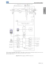
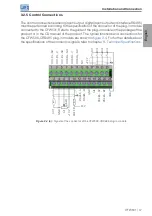
The number of analog/digital inputs/outputs, as well as other resources, may vary according to the plug-in module used. For
further information, refer to the guide supplied with the accessory or the CD-ROM.
(**)
Not available in frame A.
Figure 2.2:
Block diagram of CFW501 for Frame D
Содержание CFW501
Страница 2: ...User s Manual Series CFW501 Language English Document 10001991016 04 Models Frame A D Date 06 2015...
Страница 46: ...Manual del Usuario Serie CFW501 Idioma Espa ol Documento 10001991016 04 Modelos Tam A D Fecha 06 2015...
Страница 90: ...Manual do Usu rio S rie CFW501 Idioma Portugu s Documento 10001991016 04 Modelos Mec A D Data 06 2015...