background image

WELD THE WORLD

Cod. 006.0001.1960

03/05/2019 V.2.2

Discovery 172T

37

ENGLISH


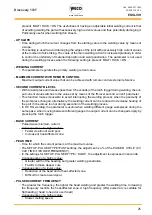
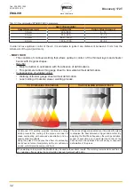
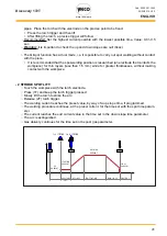
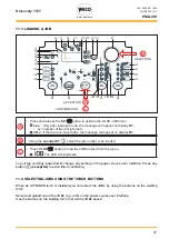
2nd  STROKE

SLOPE

SLOPE

POST GAS

WELDING

CURRENT

UP

3rd STROKE

DOWN

FINAL
CURRENT

4th STROKE

STARTING CURRENT

1st  STROKE

LIFT

 ARC STRIKE

C.C.

CURRENT

- 4 HF


○ Bring the torch up to the work until the electrode tip is approximately 2 or 3 mm away.


Press (1T) and keep the torch trigger pressed.


○ The arc strikes without contact with the part and the voltage discharges (HF) cease automatically, 

the welding current will assume the pilot current value. (if activated from the SET UP menu.)


Release (2T) torch trigger.


○ The welding current reaches the preset value, by way of a up slope time, if programmed.


○ Press (3T) trigger and keep it pressed to start the weld completion procedure.


○ The current reaches the end current value in the time set in the down slope time parameter.


○ The arc continues and the current output will be the value set in the end current parameter.


○ In these conditions the weld pool can be closed (crater filler current).


○ Release (4T) the trigger to extinguish the arc.


○ Gas delivery continues for the time set in the post gas parameter.


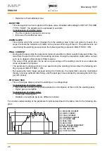
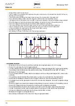
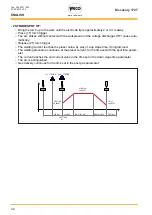
1st  STROKE

2nd  STROKE

SLOPE

SLOPE

POST GAS

PRE-GAS

WELDING

CURRENT

UP

3rd STROKE

DOWN

FINAL
CURRENT

4th STROKE

HF

ARC STRIKE

STARTING CURRENT

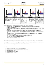
4 STROKE B-LEVEL LIFT: 


○ Touch the workpiece with the torch electrode.


Press (1T) and keep the torch trigger pressed.

Содержание Discovery 172T

Страница 1: ...Cod 006 0001 1960 03 05 2019 V 2 2 Discovery 172T Instruction manual ENG...

Страница 2: ...WELD THE WORLD Cod 006 0001 1960 03 05 2019 V 2 2 Discovery 172T 2 ENGLISH...

Страница 3: ...FIRST LEVEL MENU 17 8 2 MMA WELDING SECOND LEVEL MENU 19 8 3 MMA WELDING SPECIAL FUNCTIONS 21 9 DC TIG WELDING 22 9 1 DC TIG WELDING FIRST LEVEL MENU 22 9 2 TIG DC WELDING SECOND LEVEL MENU 27 9 3 TIG...

Страница 4: ...future consultation LEGEND DANGER This pictogram warns of danger of death or serious injury WARNING This pictogram warns of a risk of injury or damage to property CAUTION This pictogram warns of a po...

Страница 5: ...niform weld The Anti Sticking function makes it possible to detach the electrode rapidly from the workpiece in the event of accidental sticking Up to 4 00mm diameter electrode welding is possible in M...

Страница 6: ...he mains power supply to which the equipment shall be connected are given in the chapter entitled 12 TECHNICAL DATA on page 48 The machine can be connected to motor generators provided their voltage i...

Страница 7: ...AR PANEL 1 4 2 3 Welding power source ON OFF switch Item 1 Remote control connector Item 2 Connector for gas feed hose Item 3 cylinder generator Power cable Item 4 Total length including internal part...

Страница 8: ...sitive pole welding socket 6 Connect the earth clamp plug to the following welding socket Negative pole welding socket 7 Connect the earth clamp to the workpiece being processed DANGER Electric shock...

Страница 9: ...n the TIG torch 9 Connect the earth clamp plug to the following welding socket Positive pole welding socket 10 Connect the earth clamp to the workpiece being processed 11 Set the welding power source...

Страница 10: ...ut sockets L4 Illumination shows that the following function has been activated VRD reduced output volt age The no load voltage between the welding sockets is switched from U0 to Ur see technical data...

Страница 11: ...that the following parameter can be set SLOPE DOWN s L24 illumination shows that the following parameter can be set STARTING CURRENT A L25 illumination shows that the following parameter can be set P...

Страница 12: ...voltage S2 TIG Mode Press the button to select the parameter to be set Possible selections Q START DYNAMIC ARC MULTI TACK MMA mode DYNAMIC ARC S3 Press and release the button selects the first level...

Страница 13: ...your personal welding settings will be lost The reset procedure is useful in the following cases Too many changes made to the welding parameters so user finds it difficult to restore defaults Unidenti...

Страница 14: ...rce switch to I to start the equipment SIMULTANEAOUS ACTIONS Set The message will appear for a few seconds on display D1 Press the S3 button to confirm The value relative to the selected setting will...

Страница 15: ...ng flashback caused by the welding current StS SPECIAL TORCH STROKE The parameter changes the torch trigger operating mode oFF indicates standard operation 1 specifies the 4T B level management varian...

Страница 16: ...xceptions Cooling fan Make sure that the power re quired by the welding process is lower than the maximum rated power output Check that the operating con ditions are in compliance with the welding pow...

Страница 17: ...L24 L25 L17 L16 L19 80 B A ACTIVATION SELECTION C SETTING A Press the S6 button to activate the MMA mode A SYN S6 L33 L31 L32 L30 L30 MMA B Press the S3 button Use the encoder E1 to scroll the list o...

Страница 18: ...meter regulates the primary welding current value MAXIMUM CURRENT WITH REMOTE CONTROL The maximum output current value that can be achieved with foot pedal control external refer ence HOT START This p...

Страница 19: ...elected setting appears on display D1 B Using the encoder E1 edit the value of the selected setting Tab 4 Parameters of the 2nd level menu MMA mode ACRONYM LED SETTING MIN DEFAULT MAX NOTES EL ELECTRO...

Страница 20: ...VRD This parameter reduces the potential across the welding sockets when welding is not in progress The arc strike procedure is as follows Touch the workpiece with the electrode tip Raise the electro...

Страница 21: ...ings to edit The value associated with the selected setting appears on display D1 B Using the encoder E1 edit the value of the selected setting Tab 5 Special functions in MMA mode ACRONYM LED SETTING...

Страница 22: ...L7 L33 L31 L32 L30 L26 L27 L18 L22 L20 L21 L23 L24 L25 L17 L16 L19 80 C A B SELECTION SELECTION ACTIVATION D SETTING A Press the S6 button to activate the TIG mode A SYN S6 L33 L31 L32 L30 L31 CONTINU...

Страница 23: ...LT MAX USEFUL ADVICE P xx PRE GAS TIME 0 0 s 0 1 s 9 9 s Recommended value 0 3 s L16 STARTING CURRENT 5 A 50 A 170 A 2 2 50 200 2 L17 UP SLOPE 0 0 s 0 0 s 25 0 s Recommended value 0 1 s L18 WELDING CU...

Страница 24: ...ustable 4 Available when parameter PUL FA 5 Available when parameter PUL SLo 6 Available in the following mode SYNERGIC TIG The SYNERGIC PULSED TIG DC enables a highly concentrated arc to be achieved...

Страница 25: ...ameter This function makes it possible to avoid interrupting the welding process when the geometry of the workpiece changes alternatively the welding current can be reduced to decrease heating of the...

Страница 26: ...e value of this parameter can be set as a percentage of the welding current or as an absolute value expressed in Amperes The parameter is displayed but it is not used during the welding process when t...

Страница 27: ...is shown on display D1 Press the S3 button to confirm The value associated with the selected setting appears on display D1 B Using the encoder E1 to edit the value of the selected setting Tab 8 Param...

Страница 28: ...rike in the TIG welding procedure by means of a high frequency HF current discharge The high frequency arc strike HF prevents the inclusion of impurities at the start of the weld pass If set to OFF th...

Страница 29: ...IN LIFT ARC MODE 1 Position the tungsten electrode on the ignition point so that there is a dis tance of about 2 3 mm between the electrode and the workpiece 2 Touch the piece with the electrode and...

Страница 30: ...the encoder E1 edit the value of the selected setting Tab 11 Special functions in MMA mode ACRONYM LED SETTING MIN DEFAULT MAX NOTES L13 Q START 0 1 s oFF 60 s 3 See Table 12 L14 DYNAMIC ARC oFF oFF O...

Страница 31: ...processing to be carried out values between 1 A and 20 A for thin layers while a value between 20 A and 50 A for medium thick layers Welding power remains constant even when the distance between elect...

Страница 32: ...gauge sheet without deformation Less melting of material slower welding process TIG DC WELDING CONTINUOUS TIG DC WELDING WITH MULTITACK Continuous TIG welding provides continuous energy which prevents...

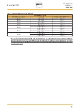
Страница 33: ...0 A 110 A 1 0 1 5 2 0 mm 110 A 130 A 1 0 1 5 130 A 150 A 1 5 2 0 2 5 mm 150 A 160 A 1 0 1 5 160 A 170 A 1 5 2 0 3 0 mm 170 A 180 A 1 0 1 5 180 A 200 A 1 5 2 0 It is recommended that a pre gas time of...

Страница 34: ...il ability of certain procedures depends on whether or not certain parameters or functions of the unit are enabled or set in the associated menus The table shows the settings to be made to enable each...

Страница 35: ...ch electrode Press 1T and keep the torch trigger pressed Slowly lift the torch to strike the arc The welding current reaches the preset value by way of a up slope time if programmed Release 2T trigger...

Страница 36: ...IKE UP SLOPE DOWN SLOPE POST GAS STARTING CURRENT WELDING CURRENT FINAL CURRENT HF 4 STROKE LIFT Touch the workpiece with the torch electrode Press 1T and keep the torch trigger pressed Slowly lift th...

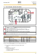
Страница 37: ...The welding current reaches the preset value by way of a up slope time if programmed Press 3T trigger and keep it pressed to start the weld completion procedure The current reaches the end current val...

Страница 38: ...DOWN FINAL CURRENT 4th STROKE SECOND CURRENT PRESS AND RELEASE STARTING CURRENT 4 STROKE B LEVEL Bring the torch up to the work until the electrode tip is approximately 2 or 3 mm away Press 1T and kee...

Страница 39: ...001 1960 03 05 2019 V 2 2 Discovery 172T 39 ENGLISH FINAL CURRENT 1st STROKE 2nd STROKE SLOPE SLOPE POST GAS PRE GAS MAIN CURRENT UP 3rd STROKE DOWN 4th STROKE HF ARC STRIKE SECOND CURRENT PRESS AND R...

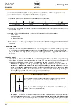
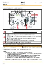
Страница 40: ...the selected setting appears on display D1 C Using the encoder E1 edit the value of the selected setting Tab 17 Parameters of the 2nd level menu 2 STROKE SPOT mode ACRONYM LED SETTING MIN DEFAULT MAX...

Страница 41: ...acts the workpiece for thin layers less than 1 5 mm while for greater thicknesses without making contact with the workpiece 2 STROKE SPOT LIFT Touch the workpiece with the torch electrode Press 1T and...

Страница 42: ...torch trigger The welding current reaches the preset value by way of a up slope time if programmed The welding procedure continues at the preset current for the time set with the spot time param eter...

Страница 43: ...current reaches the preset value by way of a up slope time if programmed The welding procedure continues at the preset current for the time set with the spot time param eter The current reaches the e...

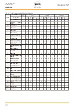
Страница 44: ...4 4 1 WELDING CURRENT TIG 1 1 1 1 1 1 1 1 1 1 1 1 1 MAXIMUM PEDAL CUR RENT IN TIG 2 2 2 2 2 2 1 SECOND WELDING CUR RENT 1 BASE CURRENT 1 PEAK TIME 1 BASE TIME 5 5 5 5 5 5 5 5 1 PULSED CURRENT FRE QUE...

Страница 45: ...4 L10 L11 L12 L29 L28 D1 S1 S2 E1 L6 S3 S4 S5 S6 L9 L8 L4 L5 L7 L33 L31 L32 L30 L26 L27 L18 L22 L20 L21 L23 L24 L25 L17 L16 L19 A B D C 3sec ACTIVATION CONFIRMATION SAVING SA SELECTION A Hold down the...

Страница 46: ...S4 button for 3 seconds to gain access to the JOB SAVE DELETE menu SA The message appears on the following displays D1 B Use the encoder E1 to select the following setting Er The message is shown on d...

Страница 47: ...ob used nO J If there are no saved jobs the message will appear on display D1 B Using the encoder E1 select the job number to be loaded C Press theS4 button to load the JOB and exit from the menu The...

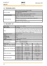
Страница 48: ...and the public system It is the responsibility of the installer or user of the equipment to ensure by consultation with the distribution network op erator if necessary that the equipment is connected...

Страница 49: ...49 ENGLISH Actual input current 40 40 C 13 2 A 50 40 C 20 4 A 60 40 C 17 3 A 13 6 A 100 40 C 20 4 A 14 6 A No load voltage U0 53 V 53 V Reduced no load voltage Ur 8 V 8 V Rated HF peak voltage Up 7 8...

Страница 50: ...WELD THE WORLD Cod 006 0001 1960 03 05 2019 V 2 2 Discovery 172T 50 ENGLISH 13 WIRING DIAGRAM...

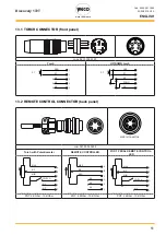
Страница 51: ...CONTROL CONNECTOR back panel E N C X F RIF MIN MAX SWITCH C D B A N C X ORCH WITH POTENTIOMETER POT 2KOhm 10KOhm REMOTE CONNECTOR D B C A E F 021 0004 0602 D F E C A B E N C X F RIF MIN MAX SWITCH C D...

Страница 52: ...WELD THE WORLD Cod 006 0001 1960 03 05 2019 V 2 2 Discovery 172T 52 ENGLISH 14 SPARES 14 1 DISCOVERY 172T...

Страница 53: ...mm 17 012 0001 0000 INTERNAL FRAMES 18 011 0006 0031 HANDLE 19 045 0002 0021 NEOPRENE CABLE 20 050 0006 0001 POWER BOARD 21 046 0002 0013 INSULATING SHEET 22 010 0007 0005 PLANAR TRANSFORMER 23 050 00...

Страница 54: ...E DESCRIPTION 021 0000 0001 TORCH CONNECTORS COMPLETE KIT 1 016 5001 0822 SLEEVE HOSE ADAPTOR 1 4 2 016 0007 0001 HOSE CLAMPS 11 13 3 016 0007 0709 HOSE CLAMP 07 09 4 016 5001 0821 SLEEVE HOSE ADAPTER...

Страница 55: ...WELD THE WORLD Cod 006 0001 1960 03 05 2019 V 2 2 Discovery 172T 55 ENGLISH...

Страница 56: ...WECO srl Via S Antonio 22 Loc Belvedere 36056 Tezze sul Brenta Vicenza Italy Tel 39 0424 561 943 fax 39 0424 561 944 www weco it Cod 006 0001 1960 03 05 2019 V 2 3...

Отзывы: