background image

8

http://support.weathermatic.com

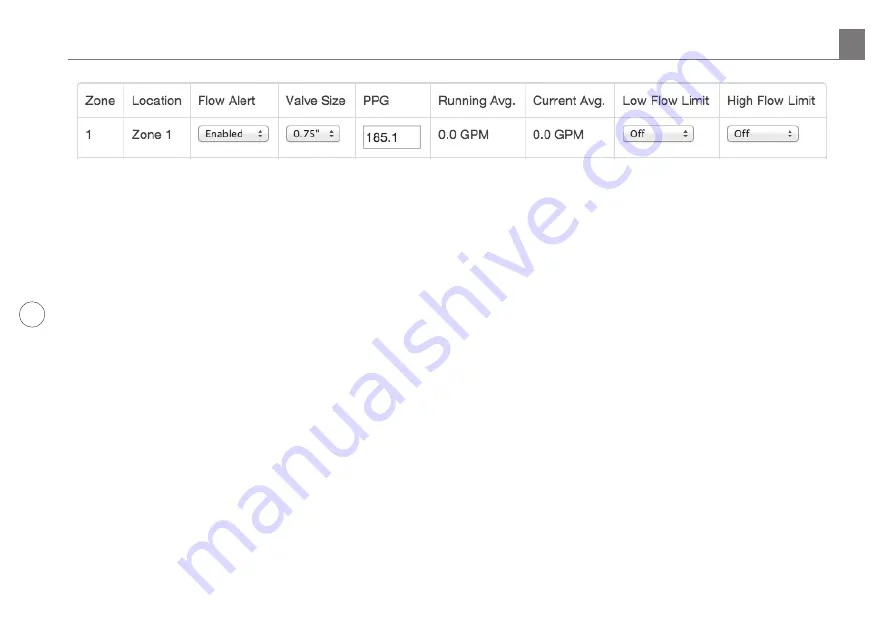
2.  Flow Alert column:  Here you can choose between 

“Enabled” and “Disabled” per zone. If you selected 
“Disabled”, it means that zone will NOT shut down 
for out-of-tolerance flow conditions. SmartLink Flow 
Aircard will still continue to calculate flow statistics for 
the zone and they will be displayed on the web screen 
and in the “Reports” section of SmartLink. 

3.  Valve Size column: Select the size of valve on for this 

zone.  This can be done before or after flow averages 
have been established. 

4.  Low and High Limit columns: Individual zone Low/High 

Limit settings can be established two ways. 

a.  Manually select the Low and High Limits for each 

zone. Refer to the “Running Average” to gauge the 
best flow limits. Select the Low Flow Limit (in GPMs) 
then the High Flow Limit (in GPMs). Be mindful that 
false alarms can occur if the Flow Limits are set too 
close to the “Running Average”.

a.  Or allow the SmartLink Flow Aircard to 

automatically set the “Low/High Flow Limits” by 
using the “Low/High Flow Tolerance” % settings 
you entered earlier in the “Global Flow Settings”. 
This will calculate the “Low/High Flow Limits” from 

the “Running Average” automatically. For example, 
if a zone’s “Running Average” is 100GPM and the 
“Global Low/High Tolerance” was set to 25%, the 
zone’s Low and High Flow Limits would be set 
to 75GPM and 125GPM. Manually setting the Low 
and High Flow Limits, as described above (1), will 
override this.

5.  Click “Save” and you’ll be returned to the Flow page 

where you can review the saved information. 

What happens next?

When a zone or zones Low and High Flow Limits have 

been crossed:

 An alert will be sent to whoever is managing 

this system. Reminder: You/They must be set up to receive 
email alerts for these events in your SmartLink Account. Go 
to “My Account” to add the alerts. These alerts will also be 
viewable within SmartLink. 

When a zone or zones Low and High Flow Limits have 

been crossed:

 The affected zone/s or the entire program 

will be shutdown. 

4.0 SmartLink Network Global Flow Settings, Zone Flow Settings and Operation

Содержание SmartLink SL-AIRCARDFLOW

Страница 1: ...SmartLink Flow Aircard SL AIRCARDFLOW Owner s Manual LTE Commercial Wireless ...

Страница 2: ...c com Telephone 888 484 3776 Scan with smartphone to go to web based help www weathermatic com Introduction If you wish to install and activate this SmartLink Flow Aircard before the SLFSI Flow Sensor is installed or accessible only complete Sections 1 and 2 Complete Section 3 once you re ready to move forward with wiring the flow sensor to the Aircard and completing the SmartLink Network Flow set...

Страница 3: ...r If the controller has two RJ 11 jacks SL4800 either jack will work The jack is located in the upper right area and is black Ensure it is plugged in completely 6 Verify that all of the nearby cables are put neatly in place which will enable the panel door to close completely 7 The Aircard status LED will flash rapidly green until it cycles through the 4 status positions This will last approximate...

Страница 4: ...ed areas marked with an asterisk Note Company Name is required If creating a personal account use your name in place of the company name 2 Once logged in you will be taken to the Sites page Note Sites are like folders that contain the SmartLine or ProLine controller s 3 You can begin by adding a new Site or add the new SmartLine controller to an existing Site 4 To add a New Site for the controller...

Страница 5: ...tivated Once activated the Aircard can be moved and connected to any SmartLine controller Version 3 1 or higher If the Aircard has yet to be installed please see 1 0 Installing the SmartLink Flow Aircard 14 If any errors occur after installation and activation on the SmartLink Network see Step 5 0 Troubleshooting or contact our Help Desk for further assistance 15 Once the Aircard is activated you ...

Страница 6: ...es The Flow Sensor must be installed in accordance with the minimum distances that are shown in the installation diagram 3 Install an adequately sized valve box over the Flow Sensor for proper maintenance access 4 Use P 39 approved underground burial cable from the Flow Sensor to the Aircard mounted next to the controller Maximum wiring distance from sensor to the Aircard is 2000 feet 610m The cab...

Страница 7: ...nce range The entire system will be shut down if it detects two zones in a row reporting flow usage outside of the user defined high low tolerance range This indicates a system mainline break has occurred With a Master Valve installed breaks in the system s mainline will be protected because the Master Valve is turned off when the alert occurs Systems without a Master Valve installed will still re...

Страница 8: ...w Sensor information PPG for other compatible Flow Sensor brands 3 Line Fill Time Choose the length of time in seconds that it takes the main and lateral lines to charge 4 Sample Time Choose interval at which sampling of flow will occur Currently fixed at 60sec subject to change 5 Low Flow Tolerance Set the of low flow tolerance to be globally applied to all zones This is overridden if a Low Flow ...

Страница 9: ... 0GPM in these columns flow has not been learned SmartLink Network Global Flow Settings Zone Flow Settings and Operation 4 0 Learning Flow for the First Time a Once the Flow Settings have been applied run through a complete program cycle You can run a manual cycle or schedule a runtime to avoid watering during restricted times Make sure though that every zone has run b Current Average is calculate...

Страница 10: ...nk Flow Aircard to automatically set the Low High Flow Limits by using the Low High Flow Tolerance settings you entered earlier in the Global Flow Settings This will calculate the Low High Flow Limits from the Running Average automatically For example if a zone s Running Average is 100GPM and the Global Low High Tolerance was set to 25 the zone s Low and High Flow Limits would be set to 75GPM and ...

Страница 11: ...r it is within For more information regarding Reports click the Help tab at the top of the page 5 0 Troubleshooting Controller not supported The controller identifies as firmware version other than 3 10 or 3 13 Only 3 10 and higher are compatible and supported Contact distributor to upgrade Could not connect The connection timed out Usually this is seen when the Aircard is unplugged or requires a ...

Страница 12: ...ADSLAC MN FLOW RevC Commercial Wireless ...

Отзывы: