


3
WEATHERGUARD.COM
Installation of PowerSync RKE
SaddleBox Installation
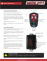
INSTALLING THE CONTROLLER AND
PAIRING THE KEYFOB
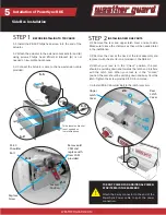
STEP 3
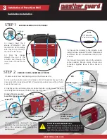
3.1 Route the actuator cable to the controller box as shown
below. Cables are shown in RED, not actual color.
3.2 Connect the power cable (with RED end) to the red Power
connector on the controller, then connect the actuator cable
to the saddlebox connector.
REPLACE COVERS
STEP 4
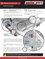
4.1 Install the linkage cover using screws (#8x1/2 Hex Head)
4.2 Reinstall the plastic guard and lock cover removed in
step 2.1 previously.
Controller Power Cable
to PowerSync Power Cable
Controller
Actuator
Cable to actuator
PowerSync
Power cable
enters box here
3.1
3.2
4.3
3.3
Connect
controller
power cable
to PowerSync
power cable.
Use 4-way
connector if
needed
PowerSync
Power cable
enters box
here
!
TO SPLIT POWER FOR ADDITIONAL POWERSYNC ITEMS IN THE SAME BOX:
Attach the 4-way connector to the end of the PowerSync Power cable to split the power connection.
Controller
3.3 Route the Power cable on the connector down the guide
channel (where the Gas Strut is installed). Connect the
controller power cable to the Power Sync Power Harness near
the grommet where the PowerSync power cable enters the
box.
3.4 To program the keyfob and to test the controller and
actuator are working properly, see Section 4 for pairing
keyfobs.
3.5 Once programed, the actuator should pull on the latch
rod. Once verified and with the keys to your box nearby, close
the truck box lid and press the button on the key fob. The
truck box lid will open. Use the provided Velcro pads to secure
the controller to the back section of the partition.