


3
WEATHERGUARD.COM
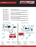
1
2
3
1
2
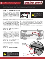
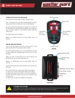
Linkage
28” Actuator
extension cable
1.1
1.4
1.3
1.2
1
2
3
1
2
1 2
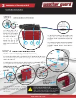
PLASTIC
GUARD
LOCK
COVER
Latch Rod Clamp
Latch Rod
Actuator assembly
Actuator cable
Extension
2.2
2.3
2.1
2.4
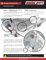
Partition wall
!
FOR STEEL SADDLEBOXES ONLY
Install the additional bridge bracket using screws
(#8x1/2 Hex Head) provided before the actuator
assembly using screws (#8x1/2 Hex Head).
Installation of PowerSync RKE
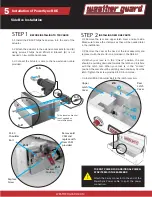
SaddleBox Installation
BEFORE ASSEMBLING TO TRUCKBOX
STEP 1
2.1 Remove lock cover and plastic guard on the driver side only.
2.4 Feed the cable underneath the latch,
but within the latch housing. Then feed the
end of the extension cable through the
partition wall.
REMOVE COVERS, ASSEMBLE ACTUATOR
STEP 2
1.3 Secure the actuator to the actuator cover
using the three screws (#10x3/4 Phillips Head)
and attach the 28 inch extension cable to the
actuator
2.2 Line up the actuator cover to the holes in front of the saddle box next to the
driver side latch. Using screws (#8x1/2 Hex Head) provided, secure the actuator
cover to the truck box.
2.3 Lightly pull to extend actuator end. Guide the latch rod clamp over the latch
rod and tighten the screws (#6-32x1/4) to the latch rod.
1.4 Connect the actuator cable to the extension
cable provided. Ensure colors of wires are
connected together (Blue to Blue, Green to
Green)
1.1 Loosely insert the 2
screws (#6-32x1/4”) into
the latch rod clamp making
sure they don’t protrude to
the inside of the clamp.
1.2 Pass the linkage
through the end of the
actuator and through the
lower hole of the latch rod
clamp.
Bridge bracket
(STEEL SADDLE
BOX ONLY)
Linkage Cover is secured
here after linkage assembly