please do not return this product to the store.
Call Us Directly! Our Trained Technicians Will Answer Your Questions and/or Ship Any Parts You May Need
You can reach us Toll Free at
1-888-827-3667
for Consumer Assistance or online at
www.wayne-dalton.com
22
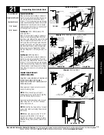
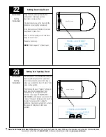
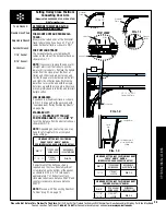
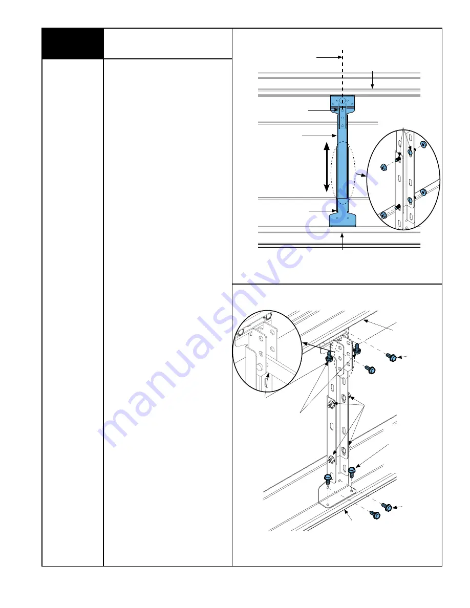
ALIGN CENTER OF BOTH TABS WITH
CENTER LINE OF TOP SECTION
CENTER LINE OF TOP SECTION
ADjuSTABLE OPERATOR BRACKET
(TOP HALF)
ADjuSTABLE OPERATOR BRACKET
(BOTTOM HALF)
top sectIon
BottoM rIB
top rIB
(4) 1/4” -20 x 9/16”
TRACK BOLTS
AND NuTS
TIGHTEN ALL (4)
TRACK BOLTS
AND NuTS
(8) 1/4” -14 x 5/8”
SELF TAPPING SCREWS
(9600 & 5140)
OR
(4) 1/4” -14 x 5/8”
SELF TAPPING SCREWS
(9100 & 5120)
(2) 1/4” -20 x 11/16”
SELF TAPPING SCREWS
(IF INSTALLING OVER u-BAR)
TyPICAL OPERATOR
ARM ATTACHMENT
BottoM rIB
top rIB
NOT uSED ON
9100 & 5120
NOT uSED ON
9100 & 5120
adjustable door Bracket option
(Models 9100, 9400, 9600, 5120 and 5140)
Tools Needed:
IMportant!
WhEN CONNECTINg A
TROllEY TYPE gARAgE DOOR OPENER TO
ThIS DOOR, A WAYNE-DAlTON OPENER/
TROllEY BRACKET MUST BE SECURElY
ATTAChED TO ThE TOP SECTION OF ThE
DOOR, AlONg WITh ANY U-BARS
PROVIDED WITh ThE DOOR. ThE
INSTAllATION OF ThE OPENER MUST BE
ACCORDINg TO MANUFACTURER’S
INSTRUCTIONS AND FORCE SETTINgS
MUST BE ADjUSTED PROPERlY.
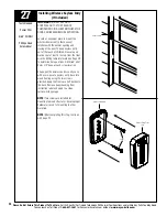
Place the top/ bottom halves of the adjust-
able operator bracket flush against the
inside of the top section (as shown). Adjust
the top/ bottom halves out against the top
and bottom rib; loosely secure both halves
together with (4) 1/4” - 20 x 9/16” track
bolts and nuts.
note:
Install the track bolts
as far apart as possible (as shown), when
positioning the top/ bottom halves together.
note:
For retro fit applications, the adjust-
able operator bracket must be aligned with
the existing operator.
note:
If a u-bar was supplied for the top
section, install the u-bar before installing the
adjustable operator bracket.
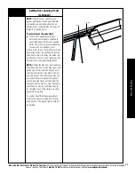
Locate the center of the top section and
align the center of both tabs of the adjust-
able operator bracket with the sections
center line; align the adjustable operator
bracket vertically.
to attach the adjustable operator
bracket:
note:
If the adjustable operator bracket will
be installed over a u-bar, use (2) 1/4” - 20
x 11/16” self drilling screws (not supplied)
instead of the 2) 1/4” -14 x 5/8” self tap-
ping screws (as shown).
Models 9100 and 5120:
Secure the adjustable operator bracket to
the top/ bottom rib with (4) 1/4” -14 x 5/8”
self tapping screws.
Models 9400, 9600 and 5140:
Secure the adjustable operator bracket to
the section and top/ bottom rib with (8) 1/4”
-14 x 5/8” self tapping screws.
Now tighten all (4) previously installed track
bolts and nuts.
I


