Next, connect to the sensors in your installation via the Click 650.656 and configure them. You’ll
want to do this before configuring the Click 650/656 itself because otherwise you’d have to re-
configure the device after you set up the sensors. Follow the steps below for each sensor in your
installation.
Connect to the Click 650/656 with your computer, laptop, or handheld device. Do this over the
Ethernet connection, or you can use one of the other communication ports on the faceplate of the
device (USB, RS-232, RS-485, or the T-bus connector which can connect to other devices). Then:
1
Open SmartSensor Manager Advance or SmartSensor Manager Matrix.
2
Under the Communications window, choose the Internet connection.
3
Enter the IP address you set up for the Click 650/656 in step 4 of this guide. Set the port in
10001.
4
With the Advance, click
Connect
. If you’re using the control bus, and you have more than one Advance, you’ll have to
select which one you want.
5
With the Matrix, click
Search
and wait for the software to find the connected sensors. (If this is the first time, or a Matrix
has just been added or replaced, choose the
Full
search. Otherwise a
Quick
search is fine.) Choose the one that you
want to configure and click
Connect
.
6
Use the software to configure the sensor’s zones, alerts (if applicable) and channels. For more information, consult that
sensor’s documentation.
7
Disconnect from the sensor when you’re done or the 650/656 will be unable to communicate with it.
5
Set up sensors
6
Connect to the web interface
1
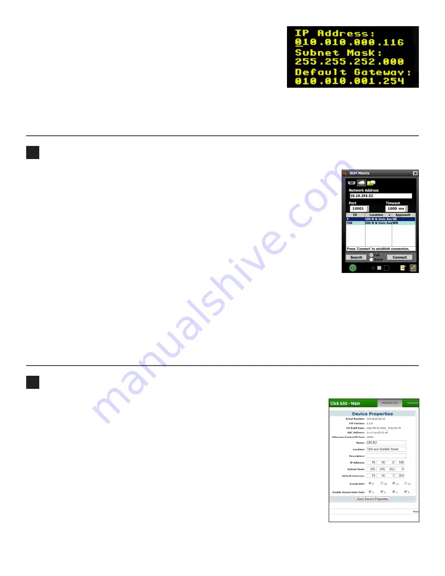
On the main screen, navigate down to Network Setup and click the
Accept
(green check mark) button to open the networking screen (shown at right).
2
Set your desired IP address by following these steps: use the left and right
arrow keys to highlight a number, then use the up and down arrow keys
to change that number. Then move to the next number. Repeat until all the
numbers are changed.
3
Press the right key one last time to navigate down to the subnet mask line.
4
Repeat steps 2 and 3 for the subnet mask and default gateway.
5
When you’re done with all three, push the check sign button to confirm your changes.
After you’re done, connect an Ethernet cable to the RJ-45 jack on the faceplate of the device to connect your Click 650/656
to your network.
Using the Click 650/656 web interface, you can map sensor channels to detector channels,
monitor the connection between the device and the sensor, and view graphs and tables
based on the last seven days of data.
To access the web interface, you’ll need to be on a computer that’s on the same network as
the Click 650/656. Open a web browser and, in the address bar, type in the IP address you
set in part 4 of this guide. When the site opens, go to the
Properties
tab. On this screen, you
can view the following info about your device:
˽
Serial Number
˽
Firmware Version
˽
OS Build Date
˽
MAC Address
˽
Ethernet/Control IP Port
You can also change the following information:
˽
Name, Location, Description
˽
IP Address, Subnet Mask
˽
Default Gateway
At the bottom is
Enable BIU
. Make sure any BIUs you intend to use are checked, and uncheck the others. Under that is
Enable
Sensor Data Port
; make sure any sensor data ports you want active are checked.


