background image


CHAPTER 4 

•  INSTALLING CLICK SUPERVISOR 

27

Use these steps to install Click Supervisor on a handheld computer:

Ensure that you have ActiveSync or Windows Mobile Device Center installed and that 

the handheld is connected to the PC and synced.

On the screen shown in Figure 4.2, click the checkbox labeled 

Pocket PC 

and then 

select 

Next > >

.

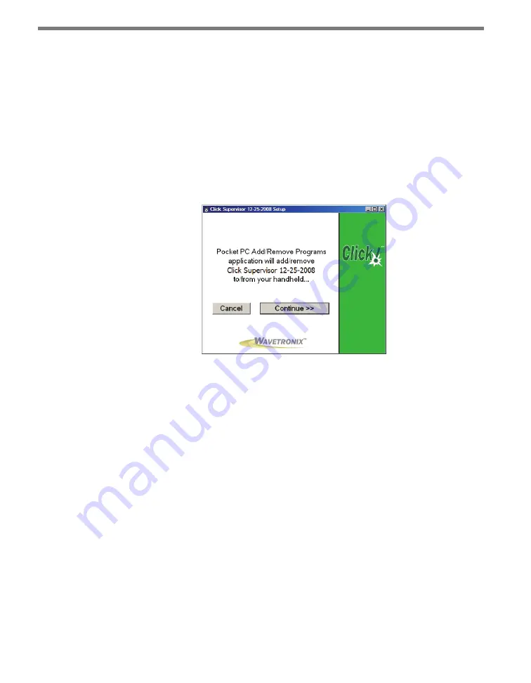
On the next screen, click 

Continue > > 

to start the installation process (see Figure 

4.5). The setup program runs the Add/Remove Programs application for Windows 

handheld devices. If a handheld device is connected to the computer, Add/Remove 

Programs will immediately begin installing Click Supervisor on the handheld device. 

If a device is not connected to the computer, Click Supervisor will be downloaded the 

next time a handheld device is connected to the computer.

Figure 4.5 – Adding Click Supervisor to a Pocket PC

Click 

OK

 once the download is complete.

Microsoft .NET Framework

The Click Supervisor setup program will automatically detect whether Microsoft .NET 

Compact Framework v1.1 is installed on your PC. If it is not installed, you will be prompted 

to install it (see Figure 4.6).

Содержание Click 500 Series

Страница 1: ...Click 500 Series USER GUIDE...

Страница 2: ...Click 500 Series USER GUIDE www wavetronix com 78 East 1700 South Provo Utah 84606 801 734 7200...

Страница 3: ...CC rules which state that operation is subject to the following two conditions 1 this device may not cause harmful interference and 2 this device must accept any interference received including interf...

Страница 4: ...cs 15 Adding a T bus to the DIN Rail 16 Mounting Click Devices 16 Wiring T buses 16 Chapter 4 Wiring the Devices 19 Working with Screw Terminal Blocks 19 RS 485 Communi cation 20 RS 232 Communication...

Страница 5: ...Vehicle Alert 53 Physical Features 54 Installation 57 Operating Modes 58 Computer Configuration 66 Connecting to a Contact Closure Device 73 Chapter 9 Click 513 Traffic Alert 75 Physical Features 76 I...

Страница 6: ...evice in a par ticular series shares common elements functions etc Click 100 series Contact closure devices Click 200 series Power and surge protection devices Click 300 series Wired communication dev...

Страница 7: ...pters in the way they are installed or the software used to configure them In the event that a Click device departs from what is written in Part I that difference will be noted in that device s chapte...

Страница 8: ...Part I Introduction to the Click Series Chapter 1 The Power Plant Chapter 2 T bus Basics Chapter 3 Wiring the Devices Chapter 4 Installing Click Supervisor Chapter 5 Using Click Supervisor...

Страница 9: ......

Страница 10: ...ecting Power 1 Power and surge protection are provided to your devices via the Click modules that make up what is known as the power plant see Figure 1 1 Assembling the power plant is the first step i...

Страница 11: ...e from the terminal block or from the AC cord into one side of the module 4 Connect power out of the other side Note It doesn t matter which side is power in as long as the opposite end is power out C...

Страница 12: ...is the AC to DC converter The Click line features several such converters The Click 201 202 204 are AC to DC power supplies that provide DC power to every Click product mounted on the DIN rail The Cli...

Страница 13: ...204 Caution Make sure power to AC mains is disconnected while wiring the AC input Wiring DC Power out of the Click 201 202 204 The screw terminals on the bottom of the devices are slightly different...

Страница 14: ...and operation of this unit Persons other than authorized and approved electrical technicians should NOT attempt to connect this unit to a power supply and or traffic control cabinet as there is a seri...

Страница 15: ......

Страница 16: ...the Click devices on the rail with only a single wiring con nection Wavetronix has two varieties of T bus connectors green connectors which conduct both power and communication and gray connectors wh...

Страница 17: ...ng motion used to connect the devices in the power plant snap the device onto the DIN rail Note All Click 500 series devices mount onto the T bus but certain other Click devices such as those in the p...

Страница 18: ...k follow these steps 1 Attach a male 5 screw terminal block to the left end of the T bus by aligning it with the first connector and pushing the modules together 2 Connect the black ground and red 24...

Страница 19: ...l need to provide power and communication to devices in your cabinet that are not on a DIN rail or on a T bus In these cases you can connect a female 5 screw terminal block to the right side of your T...

Страница 20: ...n each application s chapter in Part II of this guide Working with Screw Terminal Blocks The Click 500 series devices feature screw terminal blocks for wiring connections These screw terminal blocks s...

Страница 21: ...nal follow these steps 1 Connect the 485 white wire from the terminal block or cable to the middle screw terminal on the 5 screw terminal block connector you re using for the T bus in question see Fig...

Страница 22: ...ct to a Click device Figure 3 2 Wiring RS 485 Communication into the Click 200 Wiring RS 485 from a Click Device The Click 500 series devices also have RJ 11 jacks for RS 485 communication with a com...

Страница 23: ...ert the RS 485 communication moving to and from the T bus to RS 232 See be low for how to connect RS 232 to a laptop words Each device has screw terminals TD and RD for wiring in RS 232 The devices al...

Страница 24: ...e Alert Click 513 Traffic Alert Click 514 Event Logger In addition any custom applications developed on the Click 500 platform have the capabil ity of working with Click Supervisor if that is what the...

Страница 25: ...d from the Wavetronix website at www wavetronix com Af ter downloading the setup file double click on it to run the Click Supervisor setup wizard see Figure 4 1 Figure 4 1 Click Supervisor Setup Wizar...

Страница 26: ...processes beginning with install ing on the PC Note Although the software can be installed on most handhelds because of constantly changing handheld technologies Wavetronix can only offer technical su...

Страница 27: ...tions are complete Figure 4 4 Shortcut Options 5 Click the View release notes when finished checkbox to view the Click Supervisor release notes The release notes contain additional information about t...

Страница 28: ...e Programs application for Windows handheld devices If a handheld device is connected to the computer Add Remove Programs will immediately begin installing Click Supervisor on the handheld device If a...

Страница 29: ...k 1 Click the Install Framework button 2 Click the I Agree radio button when the License Agreement appears see Figure 4 7 Figure 4 7 Microsoft NET License Agreement 3 Click Install A window will appea...

Страница 30: ...y either a wired or wireless connection You can do this one of two ways If you are using an Ethernet connection you must be on the same network with the Click device Plug the Ethernet cable from your...

Страница 31: ...the T bus Accessing the Communication Screen To connect to your devices with Click Supervisor open the program by double clicking on it It will bring you to the Click Supervisor main screen see Figur...

Страница 32: ...andshaking Parity Allows you to set parity error checking Stop Bits Allows you to set the number of stop bits Data Bits Allows you to set the number of data bits being sent Note The flow control parit...

Страница 33: ...five digits of this number Each device on a rail must have a unique number The number it s been assigned should be unique but if it is not you can change it after connecting to the device See that de...

Страница 34: ...number for the Click 301 as well as many other such devices is 10001 The default IP address is 172 16 0 13 Once a connection is made Click Supervisor will remember the information so you don t have to...

Страница 35: ...asking if you d like to upgrade Each ver sion of Click Supervisor has the newest firmware for all the Click devices and when it connects to a device it will check to see if the firmware in the progra...

Страница 36: ...wish to open and click OK Figure 5 6 Selecting a Backup Note The default folder to save backups in is C Program Files Wavetronix ClickHome Drivers model number User If you try to save the files elsew...

Страница 37: ......

Страница 38: ...Part II Individual Click 500 Series Modules Chapter 6 Click 510 Chapter 7 Click 512 Chapter 8 Click 513 Chapter 9 Click 514...

Страница 39: ......

Страница 40: ...Operating Modes 6 The Click 510 serves as a powerful cabinet level communication troubleshooting tool It has the ability to emulate a SmartSensor 105 and to perform data integrity and data latency tes...

Страница 41: ...ation Contact Wavetronix Technical Services for support Physical Features The Click 510 physical features are used for easy installation and configuration Figure 6 2 Diagram of the Click 510 Communica...

Страница 42: ...e it can be used to convert RS 485 communications to RS 232 this is not its normal usage Instead on the Click 510 this port is normally used to upgrade the Click 510 program or reprogram the unit for...

Страница 43: ...tus as follows PWR red lights up when the device has power TD green lights up when the device is transmitting data RD yellow lights up when the device is receiving data If the Click 510 receives data...

Страница 44: ...TR pin pin 4 Other serial terminal programs like Docklight allow you to disable the DTR pin Obtain a serial terminal program and follow the distributor s instructions for installation Applications The...

Страница 45: ...his dual flashing methodology helps avoid confusion when a mode is operating and the green or yellow LEDs flicker to indicate serial data activity Operating Mode Task Selection LED State Operating LED...

Страница 46: ...hrough the second submenu 8 Release the push button once the desired submenu selection is displayed 9 Press the push button again to select the function The function will now start running Sensor Emul...

Страница 47: ...eds of 30 60 mph The first four packets show a 17 foot vehicle going 30 to 60 mph in increments of 10 mph The next four will be a 60 foot vehicle going 30 to 60 mph in increments of 10 mph This sequen...

Страница 48: ...k in your channel of communication Use it when you are connecting two Click 510 devices together or connecting a Click 510 to a computer This mode has two submenus on which you can specify the data pa...

Страница 49: ...s received by the computer the message will appear as the digits 1 8 in HyperTerminal ASCII sequence Sends an ASCII sequence a lowercase alphabet across the com munication channel This pattern should...

Страница 50: ...t to automatically discover the baud rate of a con nected sensor If so consider Autobaud the next menu option Manual baud rate configuration uses a task instead of an operating mode This means that as...

Страница 51: ...it time on each successive iteration During the discovery process the red and green system LEDs will be illuminated the green LED will flicker when serial transmit activity occurs If the discovery pro...

Страница 52: ...ed to the computer and want a general idea of the delay time you can refer to the submenu LEDs on the device The device will show results for each packet size starting with the 16 byte size shown by t...

Страница 53: ...e reset task is the sixth option presented in the menu selection process The reset function will return the Click 510 to factory defaults If a device is not responding and not commu nicating resetting...

Страница 54: ...lation Operating Modes Computer Configuration Connecting to a Contact Closure Device 7 The Click 512 monitors per vehicle lane speed length direction and class information from a SmartSensor HD Figure...

Страница 55: ...n ASCII string will be transmitted through the DB 9 port A possible application for the Click 512 is to warn specific drivers of a potentially dangerous roadway If a vehicle is detected to exceed the...

Страница 56: ...connection port The back of the Click 512 features a 5 position connector that plugs into a T bus connector and provides power and RS 485 communication to the device It also passes RS 485 com municati...

Страница 57: ...12 communicates over the RS 485 T bus to SmartSensor HD at baud rates between 9600 bps default and 115200 bps Communication to Click Supervisor is done via the RS 232 front port Device Setup Mode or R...

Страница 58: ...sh button Yellow LEDs Red LEDs Multicolored LEDs Figure 7 3 Click 512 LEDs If the Click 512 receives data via one port it will forward transmit the data to the other ports However only the RD yellow l...

Страница 59: ...ection However after a flashing mode is selected the selected mode LED will not flash the red LED will flash instead Navigating the Menu via the Push Button The menu is navigated via the push button u...

Страница 60: ...exceeds or is less than the thresholds configured for one of the eight channels The yellow row of LEDs corresponds to Click 512 channels 1 4 and the primary output LEDs 1 4 on the Click 104 The red ro...

Страница 61: ...The range to the vehicle is 163 1 feet The length based classification is group 3 A Wrong way detection event text string is illustrated in the following text string 2014 01 14 20 53 22 283 00 47 6 00...

Страница 62: ...ms of delay The ETA trigger method is recommended in order to provide a uniform experience for mo torists traveling at different speeds With this method drivers will see the sign turn on when they ar...

Страница 63: ...In this case the setback distance is specified in decimeters instead of feet Since vehicles travel at different speeds the amount of time from when the front edge of the vehicle enters the beam until...

Страница 64: ...s this increases to up to 0 038 seconds of additional delay The second method the point trigger method also provides a certain level of uniformity in that the warning sign is activated when vehicles r...

Страница 65: ...at the end of the duration The third method the ASAP trigger method provides a less uniform response because the trigger is not synchronized However this method may be useful when the setback distance...

Страница 66: ...be the option you select most often You can connect to Click Supervisor over the serial RS 232 port and do necessary troubleshooting Second LED solid The second mode is a backup mode if there are no...

Страница 67: ...ing resetting the device may fix the problem Once in reset mode use submenu 1 yellow LEDs to select which level of settings should be reset First LED solid Reset all settings except serial number and...

Страница 68: ...een saved to file See Chapter 5 for more information Expert The Expert driver allows you to configure the Click 512 The driver is divided into two tabs System and 512 The System tab is divided into th...

Страница 69: ...mber is the last five digits of the serial number which can be found under the About tab or on the barcode sticker on the bottom of the device It is recommended that you do not change this number unle...

Страница 70: ...ne of these options can currently be changed you would only use this tab if you needed to look at how the device s autobaud function is currently set up Figure 7 11 Expert Driver Autobaud Tab Setting...

Страница 71: ...method the downstream loca tion may be the actual location of the roadway sign or somewhere in between If units are English this distance is in feet if Metric then the distance is in decimeters ETA ms...

Страница 72: ...ent message itself will not be reported until about one second after the back edge of the vehicle leaves the detection beam Note Invalid speed entries will show a value of 512 mph in the serial transm...

Страница 73: ...led vehicles that exceed this length will trigger an output When disabled the length threshold is ignored Duration ms An output stays on for at least the number of milliseconds speci fied here As long...

Страница 74: ...current firmware for your device Hex View changes the view of certain settings in the driver to hexadecimal Clicking the Quit menu exits the driver and returns you to the Click Supervisor main page C...

Страница 75: ......

Страница 76: ...Computer Configuration 8 The Click 513 monitors interval data from a SmartSensor HD by polling the SmartSensor HD to retrieve vehicle speed volume and occupancy data from the latest interval for up t...

Страница 77: ...help clear the congested roadway such as keeping the traffic light green so cars can clear the exit ramp or displaying a message for drivers on a dynamaic message sign DMS The Click 513 utilizes the C...

Страница 78: ...to remove pin 4 from the serial cable to prevent the device from going into Program mode If it enters Program mode all of the faceplate LEDs will turn off and power will need to be cycled on the devic...

Страница 79: ...hes on the left side of the module for programming or reprogramming the unit For all standard Click 513 applications the rest of the DIP switches are unused Warning The sixth switch of DIP switch 1 co...

Страница 80: ...Click 513 Located on the front of the module below the DB 9 connector is a push button labeled Mode Switch This push button allows you to make selections from the menu See the Op erating Modes section...

Страница 81: ...tead Navigating the Menu via the Push Button The menu is navigated via the push button using hold and press actions Hold Pressing and then holding for at least 1 seconds allows you to enter the Click...

Страница 82: ...nto readable text strings This information is forwarded as ASCII text messages over the RS 232 ports of the Click 513 The following illustrates an interval detection entry in a terminal program Figure...

Страница 83: ...hen put it in Actuation mode This can only be done when the Click 513 is in the Device Setup Mode Reset red flashing The red flashing mode resets the Click 513 to factory defaults If a device is not r...

Страница 84: ...ny driver and saving them to the Click device will change those settings on all drivers The Backups option can be used to read configurations that have previously been saved to file See Chapter 5 for...

Страница 85: ...d If Click Supervisor detects a discrepancy between this version and the most current version it currently has access to you will be prompted to upgrade when you connect to the device Subnet ID Shows...

Страница 86: ...on is currently not available Data Bits Shows you the number of data bits being sent This option cannot be changed Active Port Indicates on which port you are communicating with the sensor This option...

Страница 87: ...f the sensor with which the Click device is cur rently communicating This option is currently not available Server Client Allows you to set whether the device is a server or client in a point to multi...

Страница 88: ...t Example If Alert On Time 1 and Alert Off Time 2 an alert will turn on when one interval meets the requirements and will turn off when those requirements are not met for two intervals Logic Allows yo...

Страница 89: ...qualify an interval if the total volume is above the set threshold Under Volume If enabled will qualify an interval if the total volume is below the set threshold Over Occupancy If enabled will quali...

Страница 90: ...bled will qualify an interval if the total volume is below the set threshold Over Occupancy If enabled will qualify an interval if the percentage of occupancy is above the set threshold Under Occupanc...

Страница 91: ...ing this will open a directory box allowing you to name your settings file This file will always be saved in the Wavetronix folder created when you installed Click Supervisor under Wavetronix ClickHom...

Страница 92: ...CHAPTER 8 CLICK 513 91 view of certain settings in the driver to hexadecimal Clicking the Quit menu exits the driver and returns you to the Click Supervisor main page...

Страница 93: ......

Страница 94: ...ion 9 The Click 514 monitors individual vehicle data pushed from a SmartSensor HD and for wards it as tabular ASCII data to serial data logger devices Figure 9 1 Click 514 The Click 514 has been speci...

Страница 95: ...pervisor is easy to setup and use The Click 514 also performs time synchronization between the devices and converts SmartSensor HD UTC timestamps into local time The Click 514 can also be used with so...

Страница 96: ...LEDs will turn off and power will need to be cycled on the device The RS 232 and RS 485 communication ports can be accessed via the screw terminal blocks on the top of the device The first block has 4...

Страница 97: ...g Modes section of this chapter for more information The system LEDs multicolored bank in the middle of the module have dual functions they are activity indicators reporting system status information...

Страница 98: ...sure that the Click 514 is installed on a T bus with active power and RS 485 com munication The RS 232 DB 9 port on the front of the device is first used to make a connection between the Click 514 an...

Страница 99: ...complete properly Operating Modes The Click 514 has a three operating modes Logging mode Device Setup mode and Pro gramming mode different from Program mode The modes must be used in this order Device...

Страница 100: ...he desired mode see Table 11 1 3 Press the push button again to select the mode Once selected the mode will either start running or if there are submenu options the first submenu yellow LEDs will star...

Страница 101: ...er changer Figure 9 5 Connecting to the DataBridge Once connected to the configuration port select Programming mode yellow solid using the mode switch Then press the push button and you will see the y...

Страница 102: ...ts easily into programs like Notepad and Excel Figure 9 6 Data in Notepad The above figure presents the data using Notepad and the columns are as follows Date Timestamp of event YYYY MM DD hh mm ss ff...

Страница 103: ...st LED solid Reset all settings except serial number and XML variable map Second LED solid Reset all settings except serial number After being reset the Click 514 will return to the last mode that it...

Страница 104: ...ny driver and saving them to the Click device will change those settings on all drivers The Backups option can be used to read configurations that have previously been saved to file See Chapter 5 for...

Страница 105: ...d If Click Supervisor detects a discrepancy between this version and the most current version it currently has access to you will be prompted to upgrade when you connect to the device Subnet ID Shows...

Страница 106: ...on is currently not available Data Bits Shows you the number of data bits being sent This option cannot be changed Active Port Indicates on which port you are communicating with the sensor This option...

Страница 107: ...not available SmartSensor ID Shows the ID number of the sensor with which the Click device is cur rently communicating This option is currently not available Server Client Allows you to set whether th...

Страница 108: ...file Selecting this will open a directory box allowing you to name your settings file This file will always be saved in the Wavetronix folder created when you installed Click Supervisor under Wavetron...

Страница 109: ...www wavetronix com...

Отзывы: