background image


Introduction 

This  meter  measures  AC/DC  Voltage,  AC/DC  Current,  Resistance,  Capacitance,  Frequency 
(electrical & electronic), Duty Cycle, Diode Test, and Continuity plus Thermocouple Temperature. 
It  can  store  and  recall  data.  It  features  a  waterproof,  rugged  design  for  heavy  duty  use.  This 
meter can send out data wirelessly and be  linked to PC.  Proper  use and care of this  meter  will 
provide many  years of reliable service. 

Safety 

This  symbol  adjacent  to another  symbol,  terminal  or operating device indicates that 
the  operator must  refer to an explanation  in the Operating  Instructions  to avoid 
personal  injury  or damage to the  meter. 

This 

WARNING

 symbol  indicates a potentially  hazardous  situation,  which  if not 

avoided, could  result  in death  or serious injury. 

This 

CAUTION

 symbol  indicates a potentially  hazardous  situation,  which  if not 

avoided, may  result  damage to the  product. 

This  symbol  advises the user  that  the  terminal(s)  so marked must  not  be connected 
to a circuit point  at which  the voltage  with  respect to earth  ground  exceeds (in  this 
case) 1000 VAC or VDC. 

This  symbol  adjacent  to one or more terminals  identifies them  as being associated 
with  ranges that  may,  in normal  use,  be subjected  to particularly  hazardous 
voltages.  For maximum  safety,  the  meter and  its test leads should  not be handled 
when  these terminals  are energized. 

This  symbol  indicates that  a device is protected throughout  by double  insulation  or 
reinforced  insulation. 


PER IEC1010 OVERVOLTAGE INSTALLATION CATEGORY 

O

VERVOLTAGE 

C

ATEGORY 

Equipment  of OVERVOLTAGE CATEGORY  I  is equipment  for connection  to circuits in which 
measures  are taken  to limit the  transient  overvoltages  to an appropriate low  level. 
Note 

– Examples include protected electronic circuits. 

O

VERVOLTAGE 

C

ATEGORY 

II 

Equipment  of OVERVOLTAGE CATEGORY  II  is energy-consuming  equipment  to be supplied 
from the  fixed installation. 
Note 

– Examples include household,  office, and laboratory  appliances. 

O

VERVOLTAGE 

C

ATEGORY 

III 

Equipment  of OVERVOLTAGE CATEGORY  III  is equipment  in fixed installations. 
Note 

– Examples include switches in the fixed installation  and some equipment for industrial  use 

with  permanent  connection  to the fixed installation. 

O

VERVOLTAGE 

C

ATEGORY 

IV 

Equipment  of OVERVOLTAGE CATEGORY  IV  is for use at the  origin of the  installation. 

Note 

– Examples include electricity  meters and primary over-current  protection equipment 

WARNING 

CAUTION 

MAX 
1000V


Содержание 98

Страница 1: ...True RMS Industrial Multimeter MODEL WAVECOM 98 10A mA A Wavecom Instruments Pty Ltd 257 Grange Road FINDON SA 5023 P 61 08 8243 3500 F 61 08 8243 3501 sales wavecom com au www wavecom com au...

Страница 2: ...2...

Страница 3: ...minals identifies them as being associated with ranges that may in normal use be subjected to particularly hazardous voltages For maximum safety the meter and its test leads should not be handled when...

Страница 4: ...n nano 10 9 capacitance micro 10 6 amps cap m milli 10 3 volts amps A Amps k kilo 103 ohms F Farads capacitance M mega 106 ohms Ohms PEAK Peak Hold Hz Hertz frequency V Volts Percent duty ratio REL R...

Страница 5: ...na plug into the negative COM jack Insert the red test lead banana plug into the positive V jack 3 Touch the black test probe tip to the negative side of the circuit Touch the red test probe tip to th...

Страница 6: ...e main display 7 Press the MODE button again to indicate 8 Read the of duty cycle in the main display 9 Press EXIT for 2 seconds into the function of AC DC Test DC and AC TRUE Rms mV VOLTAGE MEASUREME...

Страница 7: ...nger than 30 seconds Exceeding 30 seconds may cause damage to the meter and or the test leads 1 Insert the black test lead banana plug into the negative COM jack 2 For current measurements up to 4000...

Страница 8: ...is best to disconnect one side of the part under test so the rest of the circuit will not interfere with the resistance reading 5 Read the resistance in the display CONTINUITY CHECK WARNING To avoid e...

Страница 9: ...icate near 0V and an open device will indicate OL in both polarities CAPACITANCE MEASUREMENTS WARNING To avoid electric shock disconnect power to the unit under test and discharge all capacitors befor...

Страница 10: ...s 5 Read the temperature in the display Note The temperature probe is fitted with a type K mini connector A mini connector to banana connector adaptor is supplied for connection to the input banana ja...

Страница 11: ...de The display icon MAX will appear The meter left auxiliary display will display and hold the maximum reading and will update only when a new max occurs The display icon MIN will appear The right aux...

Страница 12: ...XX which states current storage serial number Then press button PEAKHOLD to change into the initial serial number 0000 Press again it will change back On the right upper corner of LCD shows XXXX which...

Страница 13: ...entation and choose the appropriat e driver for your PC Operating System 3 Connect the USB Wireless Receiver to your PC 4 Double click the multimeter icon or access from the Start menu on your PC and...

Страница 14: ...parameter 2 Press SET button continuously to switch to setting content till exiting set up to testing mode So the updated setting content is saved If press EXIT button in this period all setting can...

Страница 15: ...chemicals cleaning solvents or detergents 5 USE ONLY FRESH BATTERIES OF THE RECOMMENDED SIZE AND TYPE Remove old or weak batteries so they do not leak and damage the unit 6 IF THE METER IS TO BE STOR...

Страница 16: ...the battery 4 Remove the six A screws securing the rear cover 5 Gently remove the old fuse and install the new fuse into the holder 6 Always use a fuse of the proper size and value 0 5A 1000V fast bl...

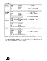
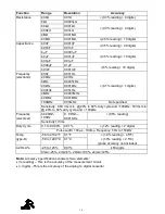
Страница 17: ...ent 400 A 0 01 A 1 0 reading 3 digits 4000 A 0 1 A 40mA 0 001mA 400mA 0 01mA 10A 0 001A 20A 30 sec max with reduced accuracy AC Current AC DC 50 to 1000Hz 400 A 0 01 A 1 5 reading 30digits 4000 A 0 1...

Страница 18: ...40MHz 0 001MHz 100MHz 0 01MHz Not specified Sensitivity 0 8V rms min 20 to 80 duty cycle and 100kHz 5Vrms min 20 to 80 duty cycle and 100kHz Frequency electrical 40 00HZ 10KHz 0 01HZ 0 001KHz 0 5 rea...

Страница 19: ...r range indication OL is displayed Auto Power Off 15 minutes approximately with disable feature Polarity Automatic no indication for positive Minus sign for negative Measurement Rate 2 times per secon...

Страница 20: ...Road FINDON SA 5023 Ph 61 08 8243 3500 Fax 61 08 8243 3501 Email sales wavecom com au Web www wavecom com au Melbourne 772A Station Street BOX HILL VIC 3128 Ph 61 03 9897 4711 Fax 61 03 9897 4766 Ema...

Отзывы: