65
Scheduled Testing, Inspection and Maintenance
1. Once de-energized and disconnected, the display will become inactive and the control box can be
opened.
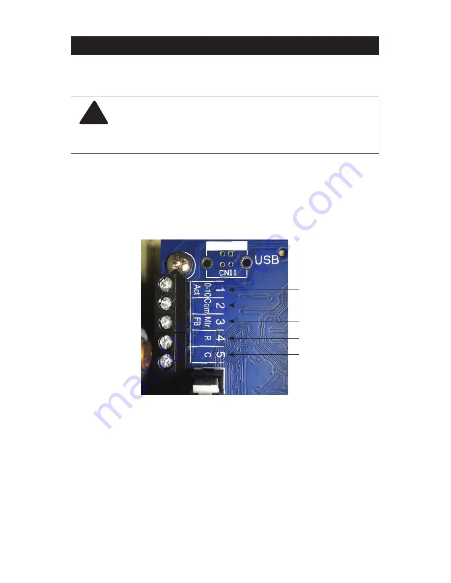
2. Using the slot screwdriver loosen terminals 1 to 5 (0-10 Act, Com, Mtr FB, R, C, respectively) in the upper
left side of the control module. Take note of the wire colors connected to each of the terminals. This
connection should be as follows:
1) Grey, 2) N/A, 3) Pink, 4) Red, 5) Black.
!
As an additional safety check, once the box is open, confirm that
the unit is de-energized by measuring the AC voltage across the
“L” and “N” terminals (46 and 45 respectively) using the voltmeter.
Alternatively, use a voltage detector to confirm that the unit is NOT
energized.
1-Grey
2-N/A
3-Pink
4-Red
5-Black
Control Unit (interior)
3. Locate the Actuator Cable. Remove the Actuator Cable from the control box and stand supports. If
needed, snip cable ties making sure not to damage any other wires when removing the cable ties.
4. Also, note the routing of the actuator cable for reinstallation.
5. Remove the actuator from the valve as follows:
a. Using the 3/8" wrench remove the two actuator support plate bolts (see image, p.73)
b. Using the 10mm wrench loosen the actuator armature clamping nut (see image, p.73)
c. Using the 3/8" wrench completely remove the support plate bolts
d. At this point the actuator should be free to slide off the valve stem away from the valve. If not, further
loosen the actuator armature clamping nut
e. Carefully remove the actuator and set it aside.
Содержание LFIS150
Страница 2: ......


