background image

6

IOM-A-Deringer 20/30_2.5-4


   2005 

EDP#2916002


© 2020 Watts

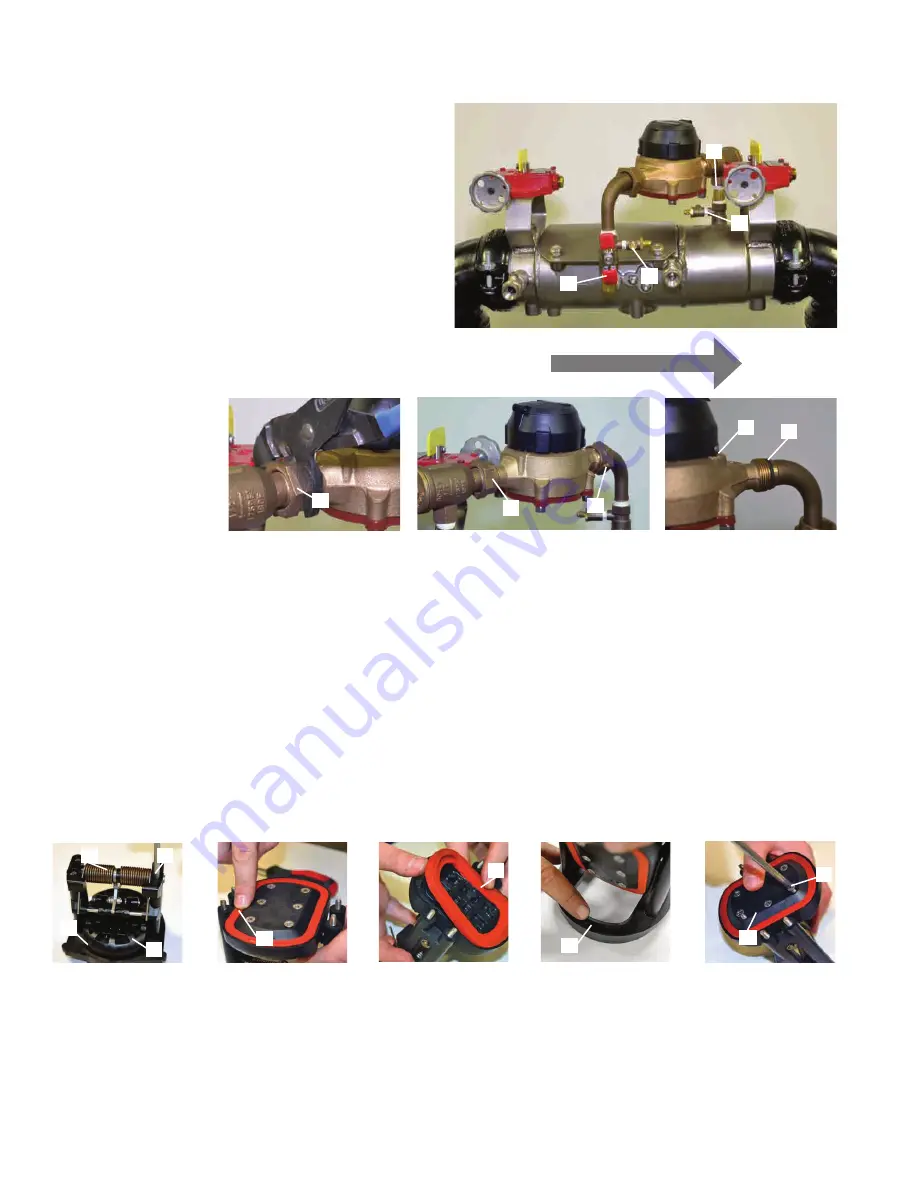
Deringer 30: Removing Bypass Meter

1.   Using the ball valve handles close the #2 bypass ball valve 

(A) and then #1 bypass ball valve (B). (Ball valve is closed 

when “T” handle is perpendicular to water flow through  

ball valve).

2.   Using a #2 flat head screw driver open bypass test cock 

#2 (C) and then open bypass test cock #1 (D). (Test cock is 

open when screw driver slot is parallel to water flow through 

test cock).

3.   Using large adjustable pliers or a wrench, unscrew and 

retract bypass meter coupling nuts (E) .  Remove the  

gaskets (F) on both sides of bypass meter.

4.   Gently remove bypass meter (G) from line. It is OK if the 

bypass fittings move slightly during the removal process.

5.   Reverse order of above instructions to reinstall bypass 

meter. Remember to install gaskets (F) before threading 

meter coupling nuts into place. 

B

C

E

E

G

F

E

FLOW

D

A

Maintenance of First Dual-action Check Module

1.   Use a #2 phillips head screwdriver to remove tower  

screws (A) from the first check seat (B) the double  

torsion spring is captured (C) and does not to be retained 

during maintenance.

2.   After removing the tower screws (A) examine the elastomer 

disk (D) and check seat (E) for fouling or damage.

3.   Should elastomer disk (D) need replacement unscrew disk 

retainer screws (F) and remove disk retainer (G). Carefully 

remove and replace elastomer disk (D). When replacing  

elastomer disk (D) be certain that no air, water or debris is 

trapped in the clapper (H) cavity behind the elastomer disk (D). 

4.   Reverse the order of the above instructions to reassemble 

check.


•   Elastomer disk must be flat in clapper (H) cavity before 

tightening disk retainer screws (F).


•   Do not cross thread disk retaining screws (F).

F

G

E

D

D

H

B

C

A

Содержание AMES Deringer 20

Страница 1: ...ety and use information can result in death serious personal injury property damage or damage to the equipment Keep this manual for future reference You are required to consult the local building and plumbing codes prior to installation If the information in this manual is not consistent with local building or plumbing codes the local codes should be followed Inquire with governing authorities for...

Страница 2: ...n Other versions of the same tool can be used For example allen wrenches instead of allen drive sockets Tools Required T45 Torx Wrench Wood Block 2 x 4 x 5 Wood Block 1 x 2 x 16 2 Phillips Head Screwdriver 2 Flathead Screwdriver 5 8 Ratchet Wrench Adjustable Wrench Deringer Test Cock Wrench Slip Joint Pliers ...

Страница 3: ... opening test cocks water will be released Take precautions to ensure discharging water does not damage the surrounding area equipment or create an unsafe condition 1 DO NOT OPEN Main test cock number 1 as it is still subject to line pressure 2 Using the DeringerTM test cock wrench or a small adjustable wrench open A main test cock number 4 Test cock is open when wrench flats are parallel to water...

Страница 4: ...nner wall of the valve body B 2 Insert a flathead screwdriver between the inner valve body and the first check module flange C gently push the first check module in the downstream direction until the first check module can easily be removed from the access port by hand B Removing the Second Dual action Check Module FLOW C A 1 Remove 1st check prior to removing 2nd check as described above 2 Use a ...

Страница 5: ...seat Do not remove unless the seat cage is being replaced 6 Reverse the order of above instructions to reassemble bypass check Valve A Part 2 1 To replace a damaged red silicone poppet disk use a 2 phillips head screwdriver to remove the disk retaining screw A 2 Remove disk retaining washer B 3 Use a flathead screwdriver to remove the gasket from poppet cavity C 4 Install new red silicone poppet d...

Страница 6: ...o reinstall bypass meter Remember to install gaskets F before threading meter coupling nuts into place B C E E G F E FLOW D A Maintenance of First Dual action Check Module 1 Use a 2 phillips head screwdriver to remove tower screws A from the first check seat B the double torsion spring is captured C and does not to be retained during maintenance 2 After removing the tower screws A examine the elas...

Страница 7: ... A examine the elastomer disk D and check seat E for fouling or damage 3 Should elastomer disk D need replacement unscrew disk retainer screws F and remove disk retainer G Carefully remove and replace elastomer disk D When replacing elastomer disk D be certain that no air water or debris is trapped in the clapper H cavity behind the elastomer disk D 4 Reverse the order of the above instructions to...

Страница 8: ...h F against the backside of the second check seat ring G Using a 1 x4 piece of wood cut to 16 length H as a lever between access port wall the 2 x4 F gently move the second check module A into its fully seated position 3 Be certain second check module A is fully seated and check O ring E is NOT fish mouthed or damaged 4 Tighten the second check retaining screws I ONLY AFTER the first check module ...

Страница 9: ...ed 4 Now fully tighten the first and second check retaining screws I The first check module must be fully seated to ensure retainer screws do not bind against check towers Binding retainer screws against check towers will result in permanent damage to first check modules WARNING FLOW Not Binding Binding C A B E F G D NOTICE Recommended torque for the check retainer bolts is 50 ft lb I Installing A...

Страница 10: ...driver close bypass test cock number 1 and 2 B Test cock is closed when screwdriver slot on stem is perpendicular to water flow through test cock 3 Use the T handles to open bypass ball valve number 1 D and then open bypass ball valve number 2 C Ball valve is open when T handle is parallel to water flow through ball valve 4 Double check to be certain of the following All cover bolts are tightened ...

Страница 11: ...line water flow 2 As the valve fills with water air will be pushed through the test cocks Once a steady flow of water is released from the test cocks close in order 2 3 then 4 Test cock is closed when wrench flats on stem are perpendicular to water flow through test cock 3 Slowly rotate the number 2 Shutoff valve operation Handle B counter clockwise to the open position FLOW C C B NOTICE Yellow or...

Страница 12: ...ty shall constitute the sole and exclusive remedy for breach of warranty and the Company shall not be responsible for any incidental special or consequential damages including without limitation lost profits or the cost of repairing or replacing other property which is damaged if this product does not work properly other costs resulting from labor charges delays vandalism negligence fouling caused...

Отзывы: