background image

3

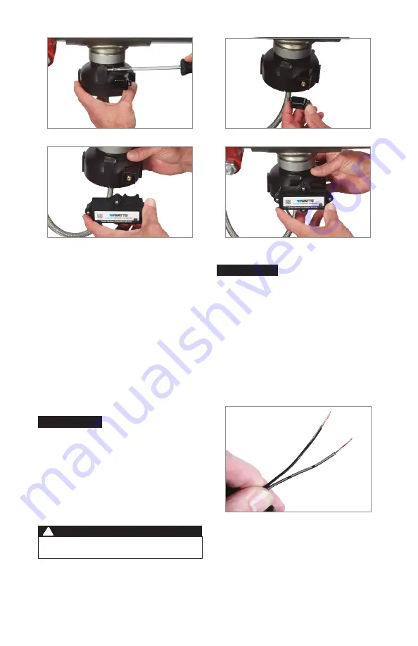
3.  Insert the bolts and tighten.

4.  Remove the dust cover from the sensor.

5.  Press the activation module onto the sensor.

6.  Check that the module is fully seated to seal the O-ring 

and to make electrical contact.

Retain the dust cover to protect the flood sensor when the 

activation module needs to be removed or replaced.

NOTICE

Attach the Activation Module Cable to the BMS Controller

The 4-conductor activation module cable should be attached to the BMS controller to transmit a nor-

mally open contact signal and provide power to the activation module. The contact signal closes 

when a discharge is detected. Follow the procedures below to connect the cable, ground wire, and 

power adapter (optional) to the controller. (See the wiring diagram for visual reference.)

To connect the cable to the controller

1.   Use the wire stripper to cut away enough insulation to 

expose 1 to 2 inches of the conductor wires.

2.   Insert the white and green wires into the input terminal.

Either the BMS power source (ranging from 12V to 24V) 

or the 24V DC power adapter provided can be used. With 

each power source, an earth ground connection is required. 
If using the optional power adapter, skip to the next set of 

instructions. Be sure to use the ground wire provided if there 

is no other earth ground on the BMS controller.

NOTICE

To use the optional 24V DC power adapter

Distinguish the positive wire from the negative one. The 

positive wire has white stripes and must be inserted into the 

power terminal; the negative wire, into the ground terminal.

1.   Connect the positive power adapter wire (black with white 

stripe) to the red wire of the activation module cable and 

insert the wires into the power terminal.

2.   Connect the negative power adapter wire (black with no 

stripe) to both the black wire of the activation module 

cable and the ground wire (if needed) then insert the 

wires into the ground terminal.

3.   Plug the power adapter into a 120VAC, 60Hz, GFI-

protected electrical outlet.

The flood sensor LED is steady green when the unit is ready.

The earth ground must be connected to the BMS controller 

before the flood sensor is put in operation.

WARNING

!

3.   Insert the red wire in the power terminal. (A power source 

ranging from 12V to 24V is required.)

4.   Insert the black wire in the ground terminal.

Содержание 957 Series

Страница 1: ...G Monitor relief valve discharge with smart and connected sen sor technology to detect flooding and trigger notification The BMS Flood Sensor Retrofit Connection Kit upgrades existing installations by...

Страница 2: ...Flood Sensor and Activation Module Attach the flood sensor and the activation module to the backflow relief valve The activation module receives a signal from the flood sensor when a discharge is dete...

Страница 3: ...r adapter provided can be used With each power source an earth ground connection is required If using the optional power adapter skip to the next set of instructions Be sure to use the ground wire pro...

Страница 4: ...rial damage from adverse water conditions chemical or any other circumstances over which the Company has no control This warranty shall be invalidated by any abuse misuse misapplication improper insta...

Страница 5: ...Surveillez l vacuation de la soupape de d charge avec la technologie de capteur intelligente et raccord e pour d tecter les inondations et d clencher la notification La trousse de raccordement de mod...

Страница 6: ...eur d inondation et le module d activation la soupape de d charge de refoulement Le module d activation re oit un signal du capteur d inondation lorsqu une vacuation est d tect e Si la d charge r pond...

Страница 7: ...peuvent tre utilis s Avec chaque source d alimentation un fil de masse est requis Si vous utilisez l adaptateur d alimentation en option passez au prochain jeu d instructions Assurez vous d utiliser l...

Страница 8: ...l eau d favorables des produits chimiques ou toute autre circonstance ind pendante de la volont de la Soci t La pr sente garantie est d clar e nulle et non avenue en cas d usage abusif ou incorrect d...

Страница 9: ...nte y conectada para detectar inundaciones y activar notificaciones El kit de conexi n de retroadaptaci n del sensor de inundaci n del BMS sistema de gesti n del edificio actualiza las instalaciones e...

Страница 10: ...ecte el sensor de inundaci n y el m dulo de activaci n a la v lvula de alivio del flujo de retorno El m dulo de activaci n recibe una se al del sensor de inundaci n cuando se detecta una descarga Si l...

Страница 11: ...V o el adaptador de alimentaci n 24 V CC suministrado Se requiere una conexi n a tierra para cada fuente de alimentaci n Si usa el adaptador de alimentaci n opcional pase al siguiente conjunto de ins...

Страница 12: ...uier otra circunstancia sobre la cual la Compa a no tenga control Esta garant a quedar anulada por cualquier abuso uso indebido aplicaci n incorrecta instalaci n o mantenimiento inadecuados o alteraci...

Отзывы: