manualshive.com logo in svg
background image

5

NOTICE

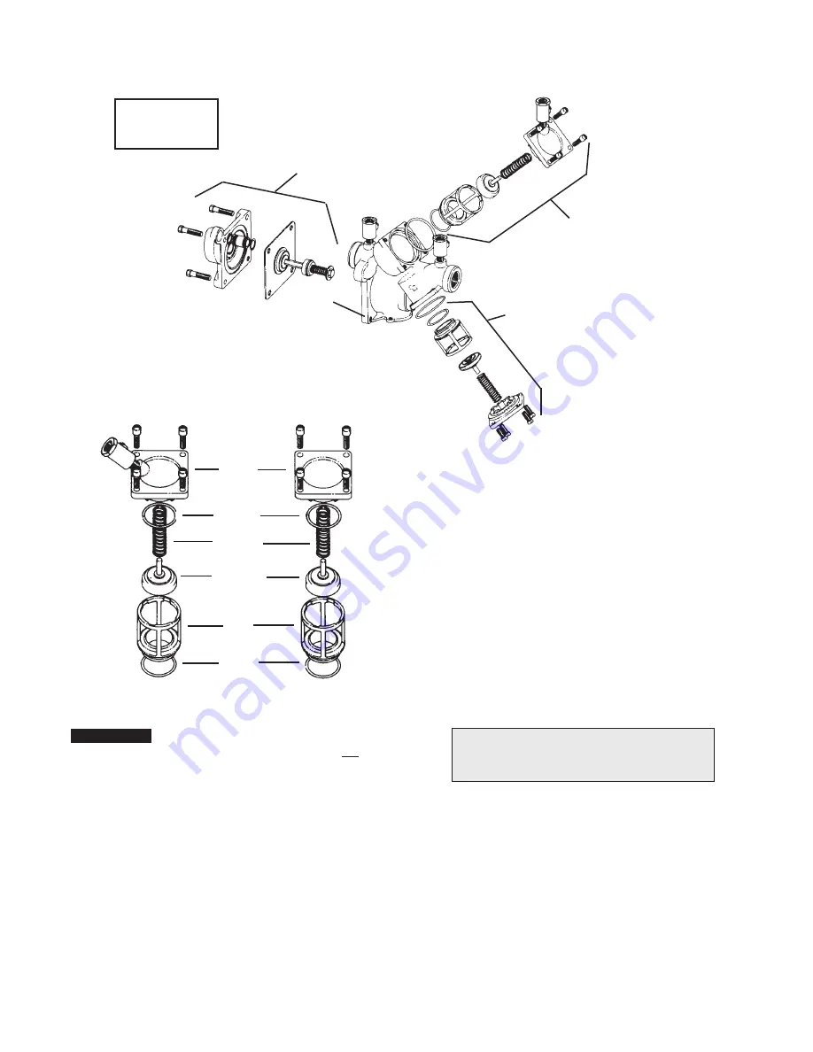
The springs and covers of the first and second check valves are 

not


interchangeable. The heavier spring loaded module should be in the first 

check and the lighter in the second check module.

Cover

Cover 

O-ring

Spring

Disc 

Assembly

Seat

Seat 

O-ring

First Check

Second Check

Servicing First and Second Check Valves 

3

/

4

" to 2"

No special tools 

required to service 

Series 909/LF909

First Check 

Service Parts Kit

Second Check 

Service Parts Kit

Body

Relief Valve  

Service Parts Kit

For repair kits and parts, refer to our Backflow 

Prevention Products Repair Kits & Service Parts 

price list PL-RP-BPD found on 

www.watts.com.

  1.  Remove the four screws holding the first check valve cover.
  2.  Lift off the first check valve cover. The check valve inside will 

come out with the cover and is attached with a bayonet type 

locking arrangement.

  3.  Holding the check valve module in both hands, rotate the 

assembly quarter turn. This will disengage the disc assembly, 

spring and seat cover into individual components.

  4.  The disc assembly may be cleaned and reassembled, or 

depending upon its condition, it may be discarded and replaced 

with a new assembly from theservice kit. O-rings should be 

cleaned or replaced as necessary and lightly greased with the 

FDA approved silicon grease which is also furnished with the 

service kit.

  5.  Reassemble the check valve module in the reverse order. 

Service is identical for both the first and second check valves.


  For further details contact your local technical sales rep-

resentative. 

Содержание 909 Series

Страница 1: ...nsistent with local building or plumbing codes the local codes should be followed Need for Periodic Inspection Maintenance This product must be tested periodically in compliance with local codes but a...

Страница 2: ...the relief valve is positioned below the first check This unique feature allows the valve to be installed either vertically or horizontally 7 Installation procedures must comply with all state and lo...

Страница 3: ...ne and in an accessible location to facilitate testing and servicing A discharge line should be piped from the air gap at the relief valve connection making sure there is adequate drainage Never pipe...

Страница 4: ...cock No 2 Step 2 Close test cock No 4 Disconnect bypass hose yellow at test cock No 4 Step 3 Open needle valve B low blue and C bypass yellow bleeding to atmosphere then closing needle valve B blue re...

Страница 5: ...ing the first check valve cover 2 Lift off the first check valve cover The check valve inside will come out with the cover and is attached with a bayonet type locking arrangement 3 Holding the check v...

Страница 6: ...misalignment Figure 1 Figure 2 Figure 3 Figure 1 To assemble the Relief Valve Assembly have a screwdriver ready Figure 2 Depress the Relief Valve Assembly carefully guiding it against the two pound s...

Страница 7: ...trically ground the piping system and or electri cally isolate the device with plastic pipe immediately upstream and down stream of the device B 6 Valve improperly reassembled B 6 If valve is dis as s...

Страница 8: ...r the cost of repairing or replacing other property which is damaged if this product does not work properly other costs resulting from labor charges delays vandalism negligence fouling caused by forei...

Отзывы: