PROGRAMMING (NOTE)
SANITIZING THE SYSTEM
12
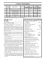
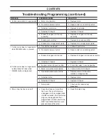
SET TIME OF DAY
The user can also set the time
of day. Time of day should only
need to be set after extended
power outages or when day-
light savings time begins or
ends. If an extended power
outage occurs, the time of day
will flash on and off which indi-
cates the time of day should
be reset.
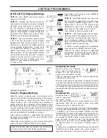
STEP 1U –
Press SET CLOCK.
STEP 2U –
Current Time (hour): Set the hour of the day
using down or up arrow buttons. AM/PM toggles after 12.
Press NEXT to go to step 3U.
STEP 3U –
Current Time (minutes):Set the minutes of
the day using down or up arrow buttons. Press NEXT to
exit Set Clock. Press REGEN to returnto previous step.
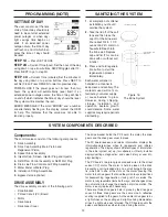
POWER LOSS If the power goes out for less than two
hours, the system will automatically reset itself. If an
extended power outage occurs, the time of day will flash
on and off which indicates the time of day should be reset.
The system will remember the rest.
ERROR MESSAGE If the word “ERROR” and a number
are alternately flashing on the display contact the OEM
for help. This indicates that the valve was not able to
function properly.
1.
At completion of softener
installation you should
sanitize the system.
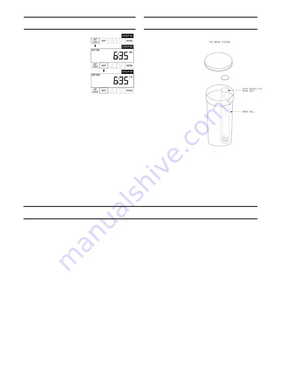
2.
Take the lid off of the salt
tank and then take the
cap off of the brine well.
Pour about 3/4 to 1 1/2
ounce of 5.25% common
household bleach into
the brine well. Replace
cap and lid. (This can be
done with or without salt
in tank.)
3.
Press and hold regenera
tion button to start the
regeneration process
immediately.
Each water softener is
handled in a manner to
keep clean and sanitary. The
materials used will not con-
taminate your water supply
or cause bacteria to grow.
However, during shipping,
storage, installation, and
operation, bacteria growth
could develop
.
Some water
supplies may require period
ic
disinfecting.
Components:
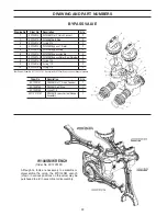
The control valve consists of the following components
1.
Drive Assembly
2.
Drive Cap Assembly, Main Piston and
Regenerant Piston
3.
Spacer Stack Assembly
4.
Injector Cap, Screen, Injector Plug and Injector
5.
Refill Flow Control Assembly or Refill Port Plug
6.
Drain Line Flow Control and Fitting Assembly
7.
Water Meter or Meter Plug
8.
Installation Fitting Assemblies
9.
Bypass Valve (optional)
DRIVE ASSEMBLY
The drive assembly consists of the following parts:
•
Drive Bracket
•
Printed Circuit (PC) Board
•
Motor
•
Drive Gears
•
Drive Gear Cover
The drive bracket holds the PC board, the motor, the drive
gears and the drive gear cover in place.
The PC board receives and retains information, displays the
information,determines when to regenerate and initiates
regeneration. The display shows different types of information
in the initial system set up (for softeners or filters), installer
displays/settings, diagnostics, and valve history or user dis-
plays/settings.
The PC board’s two-prong jack connects wires to the direct
current (DC) motor. The motor is held in place on the drive
bracket by a spring-loaded clip and a
small bulge in the plas-
tic, which fits in one of the slots on the motor housing. The
motor turns drive gears that drive the piston to cycle positions
for backwashing, regeneration, rinsing, refill or service. The
motor is fully reversible (turns both ways) and changes direc-
tion of rotation to change the direction of piston motion. The
motor is easily replaced if necessary.
There are three drive gears held in place by the drive gear
cover. All three drive gears are the same size. A reflective
coating is applied to the gears. As the center drive gear turns
a light shines on the coating and a light sensing diode deter-
mines if a light pulse was returned. The PC board counts the
pulses and determines when to stop driving the motor.
SYSTEM COMPONENTS DESCRIBED
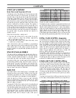
Figure 16:
The Brine System


