


Installation 13
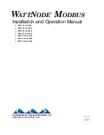
Three-Phase Four-Wire Wye
This is typically seen in commercial and industrial environments. The conductors are neutral and
three power lines with AC waveforms shifted 120° between phases. The line voltage conductors
may be connected to the
Ø
A
,
Ø
B
,
and
Ø
C
terminals in any order,
so long as the CTs are con-
nected to matching phases
. It is important that you connect
N
(neutral) for accurate measure-
ments. For wye “
-3Y
” models, the meter is powered from the
N
and
Ø
A
terminals.
Figure 5: Three-Phase Four-Wire Wye Connection
Recommended WattNode Models
The following table shows the WattNode models that should be used, depending on the line-to-
neutral voltage and line-to-line voltage (also called phase-to-phase voltage).
Line-to-Neutral Voltage
Line-to-Line Voltage
WattNode Model
120 Vac
208 Vac
WNC-3Y-208-MB
230 Vac
400 Vac
WNC-3Y-400-MB
277 Vac
480 Vac
WNC-3Y-480-MB
347 Vac
600 Vac
WNC-3Y-600-MB
Note: you may also use the following delta WattNode models to measure three-phase four-wire
wye circuits. The only difference is that delta WattNode models are powered from
Ø
A
and
Ø
B
,
rather than
N
and
Ø
A
. If neutral is present, it must be connected for accurate measurements.
Line-to-Neutral Voltage
Line-to-Line Voltage
WattNode Model
120 - 140 Vac
208 - 240 Vac
WNC-3D-240-MB
230 Vac
400 Vac
WNC-3D-400-MB
277 Vac
480 Vac
WNC-3D-480-MB
Ground
W
HI
TE
B
L
AC
K
Ø
B CT
Ø
C CT
Ø
A CT
Ø
B
Ø
C
N
Ø
A
Common
B+, D1, RxD+/TxD+
E
IA-
4
8
5
PC or Logger
A−, D0, RxD−/TxD−
Continental Control Systems LLC
Status
Status
Status
X
C
B+
A-
M
O
D
B
U
S
Com
WNC
-
WNC
-
W
ATT
N
ODE
®
M
ODBUS
-
MB
-
MB
Neutral
Phase A
Phase B
Phase C
LO
A
D
WHITE
BLACK
W
HI
TE
B
L
AC
K
LI
N
E
Source
Faces
Current
Transformers
3Y
-
xxx
3D
-
xxx


