10
❑
5)
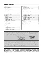
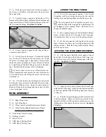
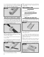
Mount the motor to the fuselage using the alu-
minum motor plate and two 2.5mm x 4mm machine
screws. Tighten the machine screws firmly to hold the
motor securely in place. See photo # 12 below.
INSTALLING THE PROPELLER & SPINNER
❑
6)
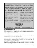
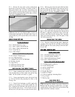
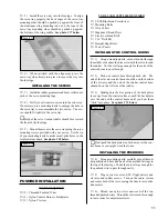
Slide the propeller onto the propeller adapter,
followed by the rear half of the spinner assembly. Slide
the flat washer up against the spinner and install the hex
nut. Tighten the hex nut firmly to hold the propeller as-
sembly in place. See photo # 13 below.
☛
When tightening the hex nut, make sure that the set
screw in the side of the propeller adapter is accessible
through the spinner opening.
❑
7)
Firmly press the front section of the spinner as-
sembly into place.
❑
8)
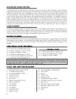
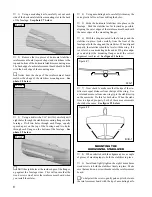
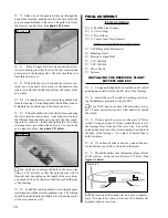
Mount the spinner assembly to the motor, mak-
ing sure you tighten the set screw in the propeller adapter
securely. See photo # 14 below.
SERVO INSTALLATION
TOOLS AND SUPPLIES REQUIRED
❑
# 0 Phillips Head Screwdriver
❑
Excel Modeling Knife
❑
Pen or Pencil
ITEMS REQUIRED
❑
{1} Foam Servo Tray
❑
{1} Servo Tray Reinforcement Board
INSTALLING THE SERVO TRAY
❑
1)
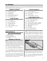
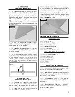
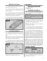
Carefully bend the sides of the servo tray rein-
forcement board up at the two precut scribe lines. See
photo # 15 below.
❑
2)
Punch out the die-cut piece of foam from the
middle of the servo tray.
❑
3)
Remove the protective backing from the rein-
forcement board. Place the servo tray onto the board,
making sure that the servo tray is lined up with the edges
of the reinforcement board.
☛
Notice that the reinforcement board is shaped at an
angle just like the servo tray. Make sure the two match.
❑
4)
Press firmly to secure the servo tray into place.
Bend down both of the outer and inner tabs and press them
into place against the servo tray. See photo # 16 below.
Photo # 12
Photo # 13
Photo # 14
❑
9)
Using a modeling knife, carefully cut out the front
of the air-scoop below the spinner assembly.
☛
Cutting open the hole in the air-scoop will allow air
to flow through the fuselage, cooling the motor, ESC
and flight battery.
Photo # 15
Photo # 16


