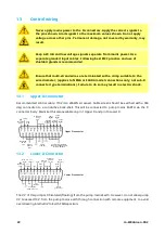
J1
J12
J13
J14
J15
2
1
J2
J3
J4
J5
J6
J7
J10
SW1
SW2
J11
J8
J9
N/O
N/C
C
N/O
N/C
C
N/O
N/C
C
N/O
N/C
C
V
mA 0V
B
0V
A
2
1
2
1
2
1
2
1
+10V
0V
i/p
0V
+12V
i/p
0V
RS485
Tube monitor Analog 2 Rem pot
Direction
enable link Analog 1 Run/stop i/p
Dose i/p
Direction i/p
Auto/man i/p
Tacho o/p
Relay 4
Relay 3
Relay 2
Relay 1
Recommended control cable: metric = 0.14 sq mm - 2.5 sq mm solid and 0.14 sq mm - 1.5 sq mm
stranded. USA = 26AWG - 14AWG solid and 26AWG - 16AWG stranded. Cable: circular. Max/min outside
diameter to ensure a seal when passed through the standard gland: 9.5 mm-5 mm.
The cable section
must be circular to ensure a seal.
Never apply mains power above 130 V AC to the terminals within the SCADA
module. Apply the correct signals to the terminals shown. Limit signals to the
maximum values shown. Do not apply voltage across other terminals.
Permanent damage, not covered by warranty, may result.
•
130 VAC Max on Relay 1-4 terminals, Dose, Auto and Start Stop
•
All others Max 30 VDC
The maximum rating on the relay contacts of this pump is 1250 VA.
Key to symbols
RUN
STOP
CLOCKWISE ROTATION
ANTI-CLOCKWISE ROTATION
INPUT
OUTPUT
MANUAL (KEYPAD) CONTROL
ANALOGUE (4-20mA/0-10V) CONTROL
AC (ALTERNATING CURRENT) INPUT
DRY (NO LEAK)
WET (LEAK DETECTED)
KEYPAD DIRECTION CHANGE
REMOTE DIRECTION CHANGE
START DOSE ON RISING EDGE
36
m-630dun-en-08.2

