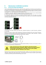
Watson Marlow Pumps 530 Series Скачать руководство пользователя страница 8

8

m-530sn-gb-02

5

Peristaltic pumps - an overview

Peristaltic pumps are the simplest possible pump, with no valves, seals or glands to clog or corrode. The fluid
contacts only the bore of a tube, eliminating the risk of the pump contaminating the fluid, or the fluid
contaminating the pump. Peristaltic pumps can operate dry without risk.

How they work

A compressible tube is squeezed between a roller and a track on an arc of a circle, creating a seal at the point
of contact. As the roller advances along the tube, the seal also advances. After the roller has passed, the
tube returns to its original shape, creating a partial vacuum which is filled by fluid drawn from the inlet port.

Before the roller reaches the end of the track, a second roller compresses the tube at the start of the track,
isolating a packet of fluid between the compression points. As the first roller leaves the track, the second
continues to advance, expelling the packet of fluid through the pump’s discharge port. At the same time, a
new partial vacuum is created behind the second roller into which more fluid is drawn from the inlet port.

Backflow and siphoning do not occur, and the pump effectively seals the tube when it is inactive. No valves
are needed.

The principle may be demonstrated by squeezing a soft tube between thumb and finger and sliding it along:
fluid is expelled from one end of the tube while more is drawn in at the other.

Animal digestive tracts function in a similar way.

Suitable applications

Peristaltic pumping is ideal for most fluids, including viscous, shear-sensitive, corrosive and abrasive fluids,
and those containing suspended solids. They are especially useful for pumping operations where hygiene is
important.

Peristaltic pumps operate on the positive displacement principle. They are particularly suitable for metering,
dosing and dispensing applications. Pumps are easy to install, simple to operate and inexpensive to maintain.

Содержание 530 Series

Страница 1: ...ecifications 13 8 1 Specification ratings 13 8 2 Weights 13 8 3 Pumphead options 14 9 Good pump installation practice 15 9 1 General recommendations 15 9 2 Dos and don ts 16 10 Pump operation 17 10 1...

Страница 2: ...4 Master dose 36 18 5 Manual dosing 40 19 Main menu 41 19 1 Security settings 42 19 2 General settings 51 19 3 Control settings 61 19 4 Help 62 20 Troubleshooting 63 20 1 Error codes 63 20 2 Technical...

Страница 3: ...27 Trademarks 85 28 Disclaimers 86 29 Publication history 87 m 530sn gb 02 3...

Страница 4: ...16 and 2004 108 EC until 19th April 2016 ROHS Directive 2011 65 EU 6 Harmonised standards used BS EN61010 1 2010 third edition Safety requirements for electrical equipment for measurement control and...

Страница 5: ...Management System ISO 9001 and the technical documentation is compiled in accordance with Annex VII B of the Directive We undertake to transmit in response to a reasoned request by the appropriate na...

Страница 6: ...4 Components supplied 530 Components 530 pump drive unit fitted with 520R2 or other pumphead if specified as a pump The designated power cable attached to the pump drive unit A 520N module providing...

Страница 7: ...il us this information and receive a RGA Returned Goods Authorisation before you despatch the product s A copy of the RGA form must be attached to the outside of the packaging containing the product s...

Страница 8: ...ller leaves the track the second continues to advance expelling the packet of fluid through the pump s discharge port At the same time a new partial vacuum is created behind the second roller into whi...

Страница 9: ...oss of product pumped and loss of production This warranty does not obligate Watson Marlow to bear any costs of removal installation transportation or other charges which may arise in connection with...

Страница 10: ...d on the pump and in the manual means Caution refer to accompanying documents This symbol used on the pump and in the manual means Do not allow fingers to contact moving parts This symbol used on the...

Страница 11: ...ocked Do not fit any devices to the drive unit other than those tested and approved by Watson Marlow Doing so could lead to injury to persons or damage to property for which no liability can be accept...

Страница 12: ...sure the pump is isolated from the mains power 2 Ensure that there is no pressure in the pipeline 3 If a tube failure has occurred ensure that any fluid in the pumphead has been allowed to drain to a...

Страница 13: ...e 2 IP IP31 to BS EN 60529 if supplied with N module then IP66 to BS EN 60529 Equivalent to NEMA 4X to NEMA 250 indoor use protect from prolonged UV exposure dB rating 530 70dB A 1m Control ratio 530...

Страница 14: ...14 m 530sn gb 02 8 3 Pumphead options 530 pump range 520R 501RL 313 314 505L 505BA 505CA 314MC 318MC...

Страница 15: ...y be set up so that the direction of rotor rotation is clockwise or counter clockwise whichever is convenient Please note however that for some pumpheads the tube life will be greater if the rotor rot...

Страница 16: ...e the pump at or just below the level of the fluid to be pumped if possible This will ensure flooded suction and maximum pumping efficiency l Do run at slow speed when pumping viscous fluids Flooded s...

Страница 17: ...ressed will perform the function displayed on the screen directly above the relevant function key and keys These keys are used to change the programmable values within the pump These keys are also use...

Страница 18: ...18 m 530sn gb 02 10 2 Starting and stopping 10 3 Using up and down keys 10 4 Maximum speed 10 5 Change rotation direction...

Страница 19: ...cting to the mains supply or the pump will be damaged Make suitable connection to an earthed single phase mains electricity supply If the pump type is one with an N module the voltage selector is not...

Страница 20: ...for the equipment The pump must be positioned so that the disconnection device is easily accessible when the equipment is in use 11 1 Conductor colour coding Conductor type European colour North Amer...

Страница 21: ...er connections are achieved between the pump and suction and discharge piping o Ensure proper connection has been made to a suitable power supply o Ensure that the recommendations in the section Good...

Страница 22: ...ogo for three seconds 13 1 Selecting the display language 1 Use the keys to select your chosen language and press SELECT 2 Your selected language will now be displayed on sceen Choose CONFIRM to conti...

Страница 23: ...rpm SG value 1 Keypad lock Disabled Auto restart OFF Analog signal type mA Analog scaling type mA Analog min current 5mA Analog max current 19mA Analog min flow rate rpm 0rpm Analog max flow rate rpm...

Страница 24: ...e pump is now ready to operate according to the defaults listed above Note The display background colour changes according to running state as follows l White background indicates pump stopped l Grey...

Страница 25: ...pump is set to operate as you require it The pump is now ready to operate All operating parameters may be changed by means of key presses see Pump operation on page 17 Power interruption This pump has...

Страница 26: ...ess MODE to display the Change mode menu Use the and keys to scroll through the available modes o Manual default o Flow calibration o MemoDose o CANCEL Use SELECT to choose mode Use the right hand fun...

Страница 27: ...st known operating state when the power was lost When the pump is running it displays an animated clockwise arrow In normal operation the direction of flow is into the bottom port of the pumphead and...

Страница 28: ...16 3 INCREASING AND DECREASING FLOW RATE Using the and keys will increase or decrease the flow rate Decreasing flow rate o A single key press will decrease flow rate by the least significant digit of...

Страница 29: ...t key presses as required to achieve the desired flow rate o Hold down the key for flow rate scrolling 16 4 MAX FUNCTION Manual mode only o Press and hold the MAX key to run at maximum flow o Release...

Страница 30: ...7 Flow calibration This pump displays flow rate in ml min 17 1 Setting the flow calibration Using the keys scroll to Flow calibration and press CALIBRATE Using the keys enter the maximum flow rate lim...

Страница 31: ...Press START to begin pumping a volume of fluid for calibration Press STOP to stop pumping fluid for the calibration m 530sn gb 02 31...

Страница 32: ...530sn gb 02 Use the keys to enter the actual volume of fluid pumped To accept the new calibration press ACCEPT or RE CALIBRATE to repeat the procedure Press HOME or MODE to abort The pump is now calib...

Страница 33: ...een dispensed the dose MemoDose mode allows the user to repeat dose a precise volume of fluid This can be achieved by dispensing a master dose or entering a dose volume manually using the keypad MemoD...

Страница 34: ...34 m 530sn gb 02 18 2 Set flow rate Using the keys scroll to Flow rate and press SELECT Using the keys enter the dose flow rate and press SELECT...

Страница 35: ...ed From the MemoDose settings screen use the keys to scroll to Resume Interrupted Dose and press ENABLE The red cross will become a green tick to indicate that Resume interrupted dose is enabled If th...

Страница 36: ...530sn gb 02 If resume interrupted doses has NOT been set the following warning screen is displayed press CONFIRM to save this setting 18 4 Master dose Using the keys scroll to Master dose and press SE...

Страница 37: ...he following screen is displayed press MANUAL to enter a dose via the keypad or DOSE to dispense a master dose Dispensing a master dose Press START to begin dispensing the Master Dose m 530sn gb 02 37...

Страница 38: ...P to finish dispensing the Master Dose Manual dose entry Press MANUAL on the master dose screen Using the keys enter the required dose volume and press SELECT to record the master dose or CANCEL to re...

Страница 39: ...record the Master Dose or CANCEL to return to MemoDose settings When MemoDose SETTINGS are complete the following screen is displayed press MEMODOSE to start in MemoDose Mode or BACK to return to Memo...

Страница 40: ...e delivered dose differs from the volume required the percentage may be adjusted within the limits 1 to 999 of the master dose Use the keys to alter the percentage The new dose size is displayed as a...

Страница 41: ...of the HOME screens or INFO screens This will display the main menu as shown below Use the keys to move the selection bar between the available options Press SELECT to choose an option Press EXIT to r...

Страница 42: ...SETTINGS from the Main menu Auto keypad lock Press ENABLE DISABLE to switch on off the Auto keypad lock When active the keypad will lock after 20 seconds of inactivity Once locked it will display the...

Страница 43: ...on off the PIN protection If PIN protection has been enabled a Master level PIN will be required to disable PIN lock Setting Master PIN Setting the Master PIN protects all functionality The Master is...

Страница 44: ...e the keys to select each digit from 0 9 Once you have the required digit press the NEXT DIGIT key After selecting the fourth digit press ENTER Now press CONFIRM to check that the number entered is th...

Страница 45: ...tionality Press NEXT to selectively enable functionality access for User 1 and User 2 Configure User 1 security settings The PIN PROTECTION level screen will be displayed with User 1 highlighted press...

Страница 46: ...To define a four digit User 1 PIN use the keys to select each digit from 0 9 Once you have the required digit press the NEXT DIGIT key After selecting the fourth digit press ENTER Now press CONFIRM to...

Страница 47: ...isable functionality highlight the enabled functionality and press DISABLE When all the required functionality has been enabled press FINISH Configure User 2 security settings The PIN PROTECTION level...

Страница 48: ...equired digit press the NEXT DIGIT key After selecting the fourth digit press ENTER To define the allowed functionality use the keys to select the functionality and press ENABLE User 2 PIN will allow...

Страница 49: ...ned functionality To enter the PIN use the keys to select each digit from 0 9 Once you have the required digit press the NEXT DIGIT key After selecting the fourth digit press ENTER If an incorrect PIN...

Страница 50: ...IN entered does not allow access to the functionality the following screen will be displayed Keypad beep From SECURITY settings scroll to Keypad beep using the keys and select ENABLE The pump will now...

Страница 51: ...was lost For example if the pump was running in analog mode prior to power loss it would return to the same operating mode and continue to run at a proportional speed to the analog input Press ENABLE...

Страница 52: ...The current chosen flow unit is displayed on the right hand side of the screen To change flow units move the selection bar over the flow unit menu entry and press SELECT Use the keys to move the selec...

Страница 53: ...abel The pump label is a user defined 20 digit alphanumeric label which is displayed in the header bar of the home screen To define or edit the pump label move the selection bar over the Pump label me...

Страница 54: ...e available characters for each digit The available characters are 0 9 A Z and SPACE Press NEXT to move onto the next character or PREVIOUS to move back to the previous character Press FINISH to save...

Страница 55: ...SETTINGS from the main menu Use the keys to move the selection bar over Pumphead type and press SELECT The following screen will be displayed Use the keys to move the selection bar over Pumphead and p...

Страница 56: ...keys to move the selection bar over the required pumphead type and press SELECT Tube size and tube material Select Tube size from GENERAL SETTINGS then use the keys to move the selection bar over Bor...

Страница 57: ...Use the keys to move the selection bar over the tube size to be used and press SELECT If a LoadSure element has been selected then the tube size is displayed as pressure and bore m 530sn gb 02 57...

Страница 58: ...screen also allows you to select the tube material used Use the keys to move the selection bar over Tube material and press SELECT Use the keys to move the selection bar over the tube material to be...

Страница 59: ...re 0 9 A Z and SPACE Press NEXT to move onto the next character or PREVIOUS to move back to the last character Press FINISH to save the entry and return to the general settings menu Restore defaults T...

Страница 60: ...equired language Press SELECT to confirm Your selected language will now be displayed on screen Press CONFIRM to continue all displayed text will now appear in your chosen language Press REJECT to ret...

Страница 61: ...s SELECT to choose the required function Speed limit The maximum speed the pump is capable of running at is 220rpm Select Speed limit from the control settings menu to define a lower maximum speed lim...

Страница 62: ...T to zero the run hours counter The run hours counter can be viewed by pressing INFO from your home screen The following screen will be displayed Press RESET to reset the run hours or CANCEL to return...

Страница 63: ...ing on the drive shaft If the pump turns on but will not run Check the remote stop function and configuration Check the mode you are in are you in analog mode Try to operate and run the pump in manual...

Страница 64: ...Power OFF ON may reset Er19 Over temperature Stop pump immediately Turn OFF Seek support Er20 Signal out of range Check analog control signal range Trim signal as required Or seek support Er21 Over si...

Страница 65: ...21 Drive maintenance There are no user serviceable parts inside the pump The unit should be returned to Watson Marlow for service m 530sn gb 02 65...

Страница 66: ...type T2 2 5A H 250V 20mm FS0064 Foot MN2507M Module seal MN2516B Module PCB SCADA MNA2066A Module PCB NEMA MNA2069A Module switch cover MN2505M Glands STD GR0056 Glands EMC GR0075 Blanking plugs GR00...

Страница 67: ...acement Always isolate the pump from the mains power supply before opening any guard or track or performing any positioning removal or maintenance operation 23 1 Pumphead replacement 520R 1 2 3 4 5 6...

Страница 68: ...ys isolate the pump from the mains power supply before opening any guard or track or performing any positioning removal or maintenance operation 24 1 Continuous tubing 520R and 520R2 1 2 3 4 5 6 7 8 9...

Страница 69: ...24 2 Tube elements Grey Beige Blue 2 bar 30psi 4 bar 60psi 7 bar 100psi 520REL 520REM and 520REH 1 2 3 4 5 Sanitary connectors 1 2 3 Industrial connectors 1 2 3 m 530sn gb 02 69...

Страница 70: ...cap and clutch boot exposure to less than one minute risk of attack Halogenated chlorinated solvents Not recommended possible risk to polycarbonate tube clamp adjusters and polypropylene tube clamp lo...

Страница 71: ...Pumphead EL 520REL EM 520REM EH 520REH 2L 520R2 10 520R 5L 505L 530 Part Code Configurator Plug options 0 no plug U UK mains plug E EU mains plug A American mains plug K Australia mains plug R Argent...

Страница 72: ...h PVC Fluorel Neoprene 0 8 1 32 13 920 0008 016 1 6 1 16 14 950 0016 016 970 0016 016 920 0016 016 3 2 1 8 16 950 0032 016 970 0032 016 920 0032 016 4 8 3 16 25 950 0048 016 970 0048 016 920 0048 016...

Страница 73: ...4 933 0064 024 913 A064 024 8 0 5 16 121 902 0080 024 933 0080 024 913 A080 024 9 6 3 8 122 902 0096 024 933 0096 024 913 A096 024 mm inch STA PURE Series PFL STA PURE Series PCS 0 8 1 32 1 6 1 16 119...

Страница 74: ...Sanitary mm inch Bioprene TL Pumpsil STA PURE Series PCS STA PURE Series PFL 3 2 1 8 16 933 0032 PFT 913 A032 PFT 920 0032 PFT 965 0032 PFT 6 4 1 4 17 933 0064 PFT 913 A064 PFT 920 0064 PFT 965 0064 P...

Страница 75: ...i pressure rated elements Industrial mm inch Marprene TM STA PURE Series PCS 3 2 1 8 16 902 H032 PFQ 960 H032 PFQ Sanitary mm inch Bioprene TM STA PURE Series PCS 3 2 1 8 16 933 H032 PFT 960 H032 PFT...

Страница 76: ...43A 520R 1 6mm wall tube MNA2001 520R2 2 4mm wall tube MNA2138A grey 520REL MNA2139A beige 520REM MNA2140A blue 520REH Rotor assembly complete with pumping rollers follower rollers and tube guide roll...

Страница 77: ...520R 520R2 520REL 520REM 520REH 8 MNA2144A 520RE Track assembly for cased pumps 9 MN2023T and MN2003T 520RE Drain port and nut Parts may be ordered individually m 530sn gb 02 77...

Страница 78: ...r 059 3022 000 530U 530Du 530Di 505LTC Tube clamp set for 505L pumphead 059 4001 000 530Di 505AS Filling stand 059 5001 000 All models 520AL Dispensing lance for use with 520AFN filling needles 059 50...

Страница 79: ...Accessory Description Part code Pump compatibility 520AD Leak detector kit 059 8131 000 530UN 530DuN 530DiN m 530sn gb 02 79...

Страница 80: ...26 1 Performance curves Flow rates of suction and discharge pressures for the pumphead at different drive speeds This data was produced pumping water at ambient temperature Marprene continuous tubing...

Страница 81: ...Marprene continuous tubing 1 6mm wall 200rpm counter clockwise rotation Marprene continuous tubing 2 4mm wall 200rpm clockwise rotation m 530sn gb 02 81...

Страница 82: ...82 m 530sn gb 02 Marprene continuous tubing 2 4mm wall 200rpm counter clockwise rotation Marprene TL element 0 2 bar 0 30psi 200rpm counter clockwise rotation...

Страница 83: ...Sta Pure element 0 2 bar 0 30psi 200rpm counter clockwise rotation Marprene TM element 2 4 bar 20 60psi 200rpm counter clockwise rotation m 530sn gb 02 83...

Страница 84: ...84 m 530sn gb 02 Sta Pure element 2 4 bar 30 60psi 200rpm counter clockwise rotation Marprene TH element 4 7 bar 60 100psi 200rpm counter clockwise rotation...

Страница 85: ...n Marlow Bioprene Pumpsil LoadSure and Marprene are trademarks of Watson Marlow Limited Fluorel is a trademark of 3M STA PURE Series PCS and STA PURE Series PFL are trademarks of W L Gore and Associat...

Страница 86: ...elieved to be correct but Watson Marlow Fluid Technology Group accepts no liability for any errors it contains and reserves the right to alter specifications without notice WARNING This product is not...

Страница 87: ...29 Publication history m 530sn gb 02 530 S SN pump First published 12 15 Issue 2 06 16 m 530sn gb 02 87...

Отзывы: