background image


RUI/Gateway & Modbus

®

 TCP  


      Configuration & Programming Example  


                 Using KEPServerEX 4.0 

Watlow  
1241 Bundy Blvd 
Winona, MN 55987 
Telephone: 507-494-5656 
© 2008 Watlow Electric Mfg Co                                2 

FM 4/08 

3. 

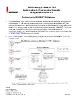
Some notables regarding the graphic above. In the steps that follow we are going to focus on 
four of the prompts shown: a. Modbus

®

 Enable (

Mb;E

) b. Gateway 

instance

 (

GTW

)  

 c. 

Gateway 

enable

 (

du;En

)  d. Modbus

®


offset

 (

M;oF

 
4. 

Notice in the graphic in step 2 that the RUI/Gateway has 2 “Com” instances. Com instance 1 

will always be Standard Bus and Com instance 2 will always be the user protocol of choice, in 
this case, Modbus

®

 TCP. This protocol when ordered also comes standard with EtherNet/IP

TM


(

I

ndustrial 

P

rotocol) as well. When setting the prompts for Com instance 2 you must first 

enable Modbus

®

 TCP, EtherNet/IP

TM

 or both. For the purpose of this paper the prompt 

displayed as 

Mb;E 

will be set to yes (Modbus

®

 TCP enabled). If a step-by-step example is 

needed to fully configure the RUI/Gateway refer to step one and download the appropriate 
user manual.  

 
5. 

To implement the network shown in step two the following settings will need to be entered: 


Further explanation of these prompts and their associated enumerated values will follow.  


6. 

After completing the configuration as shown above as well as your Com 1 settings for the  


Standard Bus side this will complete the RUI/Gateway configuration. 


7. 

Note that KEPServerEX is one of many software packages on the market today that include 
the Modbus

®

 TCP driver; this procedure is for KEPServerEX.  


8. 

The following screen shots capture a step-by-step procedure to successfully establish  


Communications between the computer (PC) running KEPServerEX and the EZ-ZONE

®


RUI/Gateway (Com instance 2) over Modbus

®

 TCP. Once communications are established  


over Com instance 2 we will then look further at the KEPServerEX configuration that will  


enable communications through the RUI/Gateway to Com instance 1 and the EZ-ZONE

®

 PM  

controls (1 - 4) over Standard Bus; thereby establishing a live and active communications link 
between dissimilar networks. 


Gateway 

Instance 

Enable 

Gateway 

Instance 

Modbus

®


Offset 

GTW

 = 1

 Du;En

 = Yes

  M;oF

 = 0


GTW

 = 2

 Du;En

 = Yes

  M;oF

 = 5000


GTW

 = 3

 Du;En

 = Yes

  M;oF

 = 

*

 10000


GTW

 = 4

 Du;En

 = Yes

  M;oF

 = 

*

 15000


* The RUI allows for a maximum entry of 9999 due to the limitations of the 7 segment display. To enter 

an offset > 9999 EZ-ZONE

®

 configurator software must be used. 

Содержание RUI/Gateway

Страница 1: ...ady been done in two other published EZ ZONE user manuals For instance if needing assistance in setting the RUI Gateway IP Internet Protocol address or if you are simply looking for general informatio...

Страница 2: ...ettings will need to be entered Further explanation of these prompts and their associated enumerated values will follow 6 After completing the configuration as shown above as well as your Com 1 settin...

Страница 3: ...ramming Example Using KEPServerEX 4 0 Watlow 1241 Bundy Blvd Winona MN 55987 Telephone 507 494 5656 2008 Watlow Electric Mfg Co 3 FM 4 08 9 Provide a name for the channel 10 In this example the device...

Страница 4: ...ple Using KEPServerEX 4 0 Watlow 1241 Bundy Blvd Winona MN 55987 Telephone 507 494 5656 2008 Watlow Electric Mfg Co 4 FM 4 08 11 Select the appropriate hardware network adapter used on the network 12...

Страница 5: ...94 5656 2008 Watlow Electric Mfg Co 5 FM 4 08 13 The next selection allows for multiple masters on the network When multiple masters exist on a network talking reading writing to the same slaves possi...

Страница 6: ...ample Using KEPServerEX 4 0 Watlow 1241 Bundy Blvd Winona MN 55987 Telephone 507 494 5656 2008 Watlow Electric Mfg Co 6 FM 4 08 15 Once the channel configuration is complete it is now time to configur...

Страница 7: ...7 FM 4 08 17 Recall that in steps 1 3 it was said that there are other configuration steps that need to be addressed that are not covered in this paper As an example of those parameters that need to b...

Страница 8: ...g KEPServerEX 4 0 Watlow 1241 Bundy Blvd Winona MN 55987 Telephone 507 494 5656 2008 Watlow Electric Mfg Co 8 FM 4 08 19 If communications fail between KEPServerEX and RUI Gateway stop polling device...

Страница 9: ...ration Programming Example Using KEPServerEX 4 0 Watlow 1241 Bundy Blvd Winona MN 55987 Telephone 507 494 5656 2008 Watlow Electric Mfg Co 9 FM 4 08 21 Use the defaults for port number and IP protocol...

Страница 10: ...6 2008 Watlow Electric Mfg Co 10 FM 4 08 23 The graphic below shows the default Modbus word order which also represents the default Modbus word order for the RUI Gateway Low High 24 Coil access is not...

Страница 11: ...xample Using KEPServerEX 4 0 Watlow 1241 Bundy Blvd Winona MN 55987 Telephone 507 494 5656 2008 Watlow Electric Mfg Co 11 FM 4 08 25 KEPServerEX allows for imported tags via a text file 26 Any tag ret...

Страница 12: ...tant to keep in mind that there is a unique Modbus address set aside for that member As an example note that as found in the EZ ZONE PM Communications user manual under the Operations Page Process Val...

Страница 13: ...61 offset 10000 PV1 of PM4 415361 offset 15000 29 Now that we know the finer details of the Modbus offset prompts lets go back to KEPServerEX and look closer at the tag configuration and properties As...

Страница 14: ...bles are configured and made available to KEPServerEX a similar screen as shown below should be displayed 32 The above examples represent tags for inputs where a similar procedure beginning at step 29...

Страница 15: ...e addresses given in defining the CLSP for each of the four PM controls 33 In the screen shot above we now see a series of inputs and outputs that have been configured within KEPServerEX To test the l...

Страница 16: ...or 80 words to any available parameter of their liking It is recommended that when doing this configuration that the parameters data type be considered It is much easier to set up a contiguous block...

Страница 17: ...ve as well the enumerated values shown in each of these Modbus registers represents the actual Modbus registers for each of the 80 corresponding Assembly Working Addresses To find what these Modbus re...

Страница 18: ...sing KEPServerEX 4 0 Watlow 1241 Bundy Blvd Winona MN 55987 Telephone 507 494 5656 2008 Watlow Electric Mfg Co 18 FM 4 08 38 Changing an element in the assembly is EZ A new tag was created as shown be...

Страница 19: ...f User Programmable Memory Blocks Again focus on the address below This particular address represents the Assembly Working Address for pointer 12 40 Now that the tags are created execute the OPC quick...

Страница 20: ...Telephone 507 494 5656 2008 Watlow Electric Mfg Co 20 FM 4 08 42 Lastly in the screen shot below notice that the 12th pointer has indeed been changed to Idle Set Point circle and the tag created to re...

Отзывы: