Safety
Introduction
Product Overview
Installation
Operation
Maintenance
Troubleshooting
Warranty
10 | 44
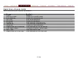
Operator Panel
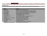
Component
Description
1 Exhaust pipe
This routes the engine exhaust to atmosphere.
2 Air intake
This brings fresh air to the engine cooling system
3 Wireless antenna
This is the antenna for the wifi system.
4 Light panel
This light illuminates the operator panel.
5
Compressor oil fill cap
This allows you to add oil to the cooler reserve.
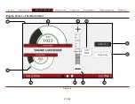
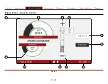
6 HMI (human machine interface)
The HMI displays information about the equipment during operation.
7 Switch panel
This panel holds the startup controls and panel light switch.
8 Electric prime button
This button initiates the pump priming process.
9 Warning panel
This panel holds the warning lights.
10 Compressor oil level window
This displays the compressor oil level.
11 Foam level LED
This displays the foam supply level.
12 Water tank level LED
This displays the water supply level.
13 Discharge 1 discharge
This is the panel mounted foam solution discharge and hose connection.
14
Tank fill valve handle
This opens and closes the valve that flows water to the tank. It recirculates the tank water or fills the tank.
15 Clear water discharge
This is the panel mounted clear water discharge and hose connection.
16 Clear water discharge valve handle
This opens and closes the valve that flows water to the clear water discharge outlet.
17 Hour meter
This measures the equipment run time.
18 Auxiliary air valve
This controls the auxiliary air outlet.
19 Auxiliary air outlet
This port provides an outlet for compressed air.
20 Suction intake
This is an intake for externally sourced water supply.
21 Tank to pump valve handle
This opens and closes the valve to flow water from the on-board tank.
22 Pump drain valve handle
This operates the valve that drains the water pump.
23 Manifold drain handle
This operates the valve that drains the manifold.
24 Foam manifold drain handle
This operates the valve that drains the foam manifold.
25 Foam generator drain handles
This operates the valve that drains the foam generator.
26 Fork lift opening
This allows a forklift to transport the equipment.
27 Serial plate
This is where the serial number is located.
28 Hold down tab
This mounts the equipment to the apparatus.
Содержание ECLIPSE CAFSystem 2.0
Страница 2: ......


