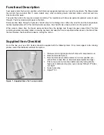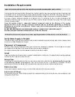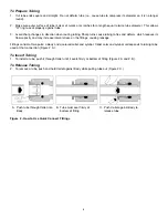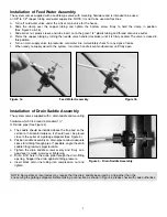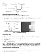
Installation of Wall Mounted Airgap™
Specifications
Location: Above RO system module and rinse water drain point.
Air Gap: 1” of free flow.
Water Flow: 0.5 gallons per minute maximum.
Inlet Tubing: 1/4” O.D. polyethylene.
Outlet Tubing: 3/8” O.D. polyethylene.
Installation Instructions
Important:
The AIRGAP™ must be installed vertically.
1.
Select location on wall or cabinet side panel.
Note:
Location must provide sufficient space to route the tubing without sharp turns. Sharp turns tend to flex and
deform the tubing, reducing its flow capacity.
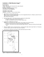
Item callouts refer to Figure A.
2.
Mount the bracket (Item 1) to the selected location according to the surface finish:
a. Rough or unfinished wood, use two screws (Item 2).
b. Smooth, use double-stick tape (Item 3). Surface must be clean.
3.
Install Tubes onto AIRGAP™ body (Item 4).
Caution:
Do not use boiling water in this procedure. Use hot water from the sink faucet only.
a. Soak one end of each tube in hot water until the plastic becomes pliant.
b. Push the ¼” tube (Item 5) all the way onto the small barb. Push the ?” tube (Item 6) all the way onto the large
barb.
4.
Attach the AIRGAP™ (Item 4) to the bracket (Item 1). Gently press the tubes into their clips. Press the 1/4” tube (Item
5) into the small clip and the 3/8” tube (Item 6) into the large clip.
5. Connect the 1/4” tube (Item 5) to the system and the 3/8” tube (Item 6) to the drain.
9
Figure A: Component Locator, Wall-Mounted Air Gap
Содержание E50TFC-3NSF
Страница 20: ...17 ...
Страница 21: ...18 Reverse Osmosis Drinking Water System Flow Diagram all models ...
Страница 23: ...20 ...


