background image

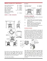
REAR FLUE EXIT

Fit the top cover plate (item 5) to the stove with the
screws holding on the rear exit cover plate (item 68).
Make sure that all the sealing rope is properly
sealed to the stove flue outlet (item 18).

HEAT SHIELD

Fit the rear heat shield as follows:  Screw the four 4”
x 1/4” bolts (item 69) to the back plate (item 23).  Fit
the four 2” spacers (item 70) over the tie bolts.  Fit
the inner heat shield (item 75) without the blanking
plate (item 72) onto the four tie bolts.  Now fit the 1”
spacers (item 71) over the tie bolts and fit the outer
heat shield panel (item 76) without the blanking plate
(item 72).  Tighten the whole assembly together
using the four 1/4” nuts provided.

FLOOR PROTECTION

When installing this heater on a combustible floor, a
floor protector, consisting of a layer of non-com-
bustible material at least 3/8” thick or 1/4” thick cov-
ered with 1/8” sheet metal is required to cover the
area under the heater and to extend to at least 18”
at the front and 8” to the sides, and embers which
may fall out from the door when stoking or fuelling.

LOCATION

There are several conditions to be considered when
selecting a location for your Waterford Erin 90 T/V &
R/V Stove.

(a)

Distance from a safe chimney.

(b)

Position in the area to be heated - central 
locations are usually best.

(c)

Allowance for proper clearances to com

bustibles.

(d)

Obstruction in the ceiling, upper floor or roof,
for example, ducting plumbing, electrical fit
tings and wiring, overhead fixed furnishings 

etc.

WARNING

DO NOT OBSTRUCT FREE AIR SUPPLY TO THE
SECONDARY AIR DUCT AT THE REAR OF THE
STOVE.

3

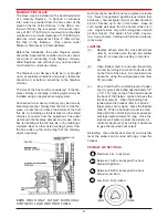
With rear heatshield fitted
for rear outlet configura-
tion.

Rear heat
shield fitted
complete with
shielded chim-
ney connector
for a rear outlet
configuration.
Chimney con-
nector and pipe
shield not sup-
plied as stan-
dard.

1 inch space

REAR

EXIT

FITTING OF REAR HEAT
SHIELD

Содержание Erin 90 T/V

Страница 1: ...guration SAFETY NOTICE Please read this entire manual before you install and use your new room heater Failure to follow instructions may result in property damage bodily injury or even death If this stove is not properly installed a house fire may result For your safety follow the installation directions Contact local building or fire officials about restrictions and installation inspection requir...

Страница 2: ...t already done so Remove the loose fitting hob and place on a non abrasive surface d Place the plastic packing on the ground at the back of the stove and lay the stove on its back on top of the packing e Remove the wooden pallet by taking out the two retaining screws from the base of the stove f Fit the four legs item 2 to the base item 1 of the stove with the four 5 8 x 5 16 screws provided Fit t...

Страница 3: ... 8 thick or 1 4 thick cov ered with 1 8 sheet metal is required to cover the area under the heater and to extend to at least 18 at the front and 8 to the sides and embers which may fall out from the door when stoking or fuelling LOCATION There are several conditions to be considered when selecting a location for your Waterford Erin 90 T V R V Stove a Distance from a safe chimney b Position in the ...

Страница 4: ... be reduced to 91 2 Pipe shield and heat shields are not supplied as standard 4 REDUCED CLEARANCES Under certain conditions the minimum clearances may be reduced by means of a Listed Waterford rear heat shield assembly installed in accordance with the manufactur ers instructions b Shields constructed in accordance with NFPA211 USA Can3 B365 installation code for solid fuel fired appliances c Fitti...

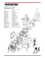
Страница 5: ...L GLASS CLIPS 39 LARGE GLASS CLIP 40 TOP COVER PLATE TO DOOR FRAME 41 BOTTOM COVER PLATE TO DOOR FRAME 42 CONTROL KNOB 43 SHAFT 44 SPACER 45 TOP AIR DUCT PLATE 46 SECONDARY AIR BAFFLE 47 SPRING 48 CLAMP PLATE TO GASKET 49 TOOL HOLDER 50 AIR WASH GASKET 51 FIRE DOOR GLASS 52 FIRE DOOR GASKET 53 ASHPIT DOOR GASKET 54 HOB GASKET 55 AIR WASH CHAMBER GASKET 57 INSIDE TOP COVER GASKET 58 BRICK CLIPS 59 ...

Страница 6: ... the bottom and top edges with at least a 1 air gap 4 All clearances shall be measured from the outer surface of the combustible material to the nearest point on the surface of the Erin 90 T V R V disregarding any intervening protection applied to the combustible material When using a manufactured wall shield system observe local building codes and by laws CHIMNEY The Waterford Erin 90 T V R V is ...

Страница 7: ...must be firmly cemented to masonry The connector may pass through walls or partitions construction of combustible material to a masonry chimney provided the connector system selected is installed in accordance with the proper clearances and conditions See figs A B C D page 8 THIMBLES Thimbles for chimneys or vent connector should be of fire clay ASTM c 315 Specifications for Clay Flue Linings galv...

Страница 8: ...penetrate chimney flue liner 4 Solid insulated listed factory built chimney length with an inside diameter 2 larger than the chimney connector and having 1 or more of insulation serving as a pass through for a single wall sheet steel chimney connector of min 24 gauge thickness with a min 2 air space between the outer wall of chimney section and combustibles Min length of chimney section shall be 1...

Страница 9: ...the chimney where necessary Burn directly on hearth do not use a grate or elevate fire Never use gasoline gasoline type lantern fuel kerosene charcoal lighter fluid or smaller liquids to start or freshen up a fire in this heater Keep all such liquids well away from the heater while it is in use Operate stove only with fuelling door and ash pit door closed This heater is hot whilst in opera tion Ke...

Страница 10: ...lue temperature at the start of a low or overnight burn are too high it will result in reducing burn time 1 Allow the fire bed to cool down 2 Re load using full length wood preferably unsplit 3 Do not pack the fuel load as high as the sec ondary air baffle item 46 at the top of the firebox 4 An air space is necessary between the fuel load and the secondary air baffle item 46 to avoid impingement o...

Страница 11: ... fully b Remove the four corner screws and clips items 38 39 and carefully remove the broken glass c Clean the glass recess in the door d Attach adhesive thermal tape to the perimeter of the replacement glass 11 e Place the thermal taped side of the glass into the firedoor recess and replace the four corner clips items 38 39 and screws f Make sure that the large corner clip item 39 is fitted in th...

Страница 12: ...sher to contend with small fires resulting from burning embers 5 A practical evacuation plan 6 A plan to deal with a chimney fire as follows In the event of a chimney fire a Notify the fire department b Prepare occupants for immediate evacuation c Close all openings into the stove d While awaiting the fire department watch for ignition to adjacent combustibles from over heated stove pipe or from h...

Отзывы: