background image


Connection Guide 
 

1. 

Mount the 4 Cameras as required and connect them to the POE Network Switch using the 

supplied Network Cables on ports 2, 3, 4, 5. 

2. 

Connect the 

48V Power Supply

 marked 

SWITCH

 to the POE Network Switch. 

3. 

Connect a Network Cable to the rear of the NVR in the socket labelled 

LAN

. Then connect the 

other end to the POE Network Switch on port 1. 

4. 

Connect the 

19V Power Supply

 labeled 

NVR

 to the NVR. 

5. 

Plug both power adaptors into a Power-point. 

6. 

The power LED at the front of the NVR should now be illuminated and the unit will make a loud 

beep sound to indicate it is powered. 

7. 

Connect the included mouse to the USB port on the front marked with a mouse symbol. 


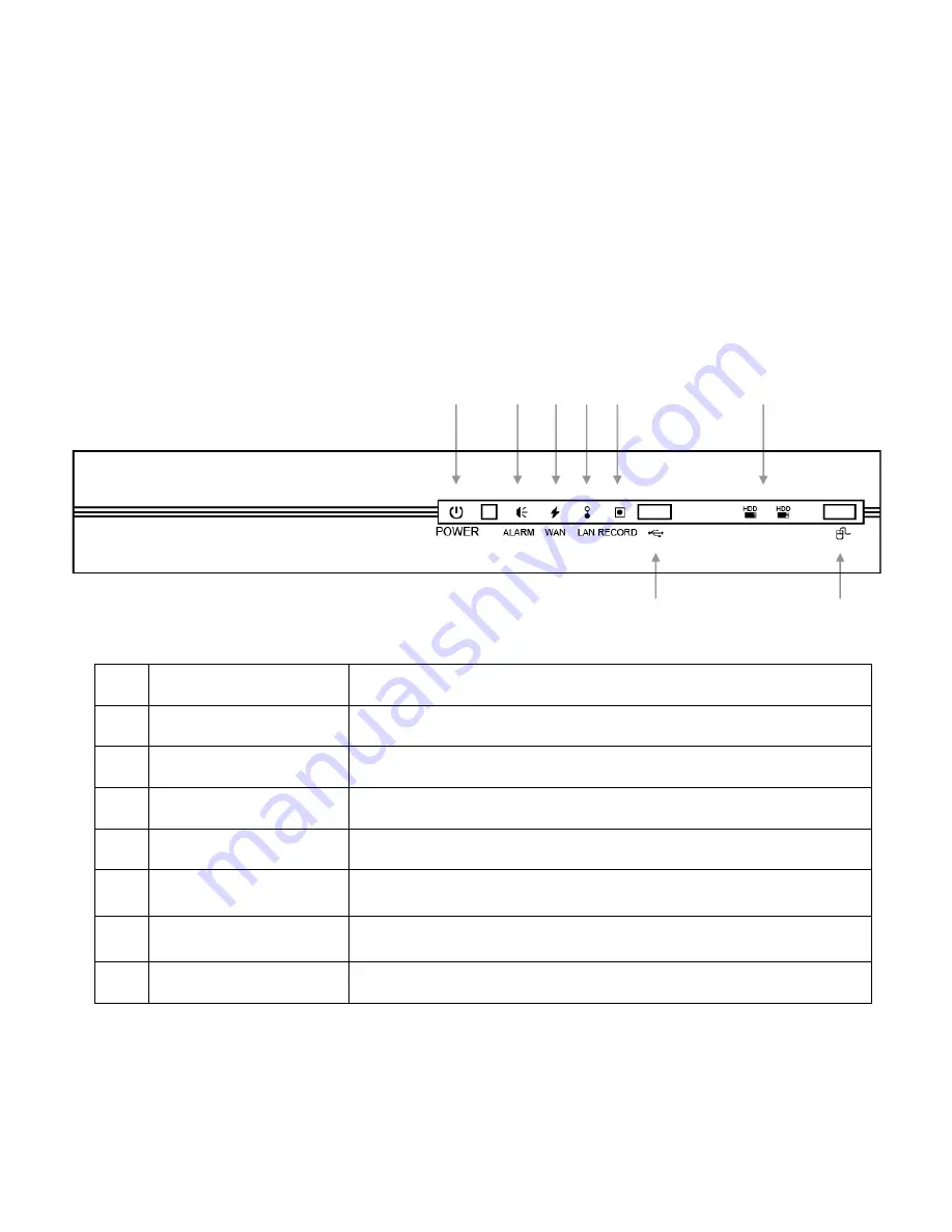
Front Panel 


POWER

”   

Indicates the NVR is plugged into power. 

ALARM

”   

Indicates that an alarm event is occurring. 

WAN

”   

Shows that the NVR is connected to the internet. 

“LAN”   

Shows that the NVR is connected to the network switch and cameras. 

“RECORD”


Indicates that the NVR is currently recording. 

“USB PORT”


A compatible USB flash drive can be plugged in for backing up 
recorded video. 

HDD1/HDD2

”   

These lights show that the Hard drives are working correctly. (The 
NVR4ENTPACK comes with one installed drive). 

“MOUSE PORT” 

Use this port to plug in a USB mouse. 


Содержание NVR4ENTPACK v1.2

Страница 1: ...iplex Operation IR Night view range of 20 metres Long Recording Duration 720p Resolution Intelligent Video Motion Detection Recording POE Network Switch Remote Network Surveillance Backup Functions Centralise your cameras away from your NVR Easy to operate with USB Mouse or IR Remote Power and video over the same cable System Auto recovery after power loss blackout View over the internet via Smart...

Страница 2: ...t Power and video over one cable 1 x POE Network switch Will Power all connected camera via POE Power Over Ethernet Connect all cameras to this switch and have the recorder in a different location 6 x Ethernet Cables Combined DC Power and Video Leads Pre terminated Allowing Simple Plug in Connection No Tools Required 2 x 1 5m 2 x 10m 1x 20m 1 x 30m Leads Supplied 1 x HDMI Connection Cable Connect ...

Страница 3: ...Unplug units before cleaning When cleaning use a damp lint free cloth only Do not expose the NVR POE Network Switch or Cameras to excessive heat cold or moisture Leave at least 50mm of space between the NVR and other objects to allow air circulation Service should be handled only by qualified technicians WARNING Please ensure you use the correct power supply for each component Plugging either Powe...

Страница 4: ...ted and the unit will make a loud beep sound to indicate it is powered 7 Connect the included mouse to the USB port on the front marked with a mouse symbol Front Panel 1 POWER Indicates the NVR is plugged into power 2 ALARM Indicates that an alarm event is occurring 3 WAN Shows that the NVR is connected to the internet 4 LAN Shows that the NVR is connected to the network switch and cameras 5 RECOR...

Страница 5: ...ither halt or reboot the system QUICK START Click to set the status display image settings and date time Click to show the channel switch panel and select the channel you want SYSTEM Click to set the system configurations Switch to the channel you want first and click to enter the zoom in mode EVENT INFORMATION Click to enter the event search menu Click to enter PTZ Mode and show the PTZ camera co...

Страница 6: ... keypad Choose QUICKSTART then TIME SETUP to set the date and time Default The default username is admin the password is also admin Users can alter the password later Please refer to the Advanced set up guide CD Important If you change the date or time on your NVR after the recording function is activated the recorded data may be deleted After setting the date and time it s recommended to clear al...

Страница 7: ...0 2 2 13 88 00 0e 53 a6 91 18 BE CONNECTED ON CH2 10 2 2 14 88 00 0e 53 a5 9f a2 UNUSED 10 2 2 15 88 00 0e 53 e1 4e k5 BE CONNECTED ON CH3 CONNECT SETUP EXIT 3 To fix the camera IP address or allow the NVR to assign an IP address to your IP camera select SETUP and select DHCP for NETWORK TYPE SETUP NETWORK TYPE DHCP IP 10 2 2 2 PORT 80 USER NAME admin PASSWORD NETMASK 255 255 255 224 GATEWAY 10 2 ...

Страница 8: ...ly in the RED zone then you should reduce the I P S even further 8 Tip You may wish to keep one camera at 10 where the quality is most important and reduce other to balance the CPU load To Begin Recording Once you have successfully set the Date and Time exit the OSD Menu by clicking the EXIT button By default the NVR will begin recording when it is properly connected to the cameras and has an inst...

Страница 9: ... twice to get 8X speed etc The maximum speed is 32X Click once to get 4X speed rewind and press twice to get 8X speed etc The maximum speed is 32X SLOW PLAYBACK Click button to get 1 2X speed playback PAUSE IMAGE JOG Click button to pause the current image displayed on the screen In the Pause mode Click once to get one frame forward Click once to get one frame rewind STOP Pressing button under all...

Страница 10: ...ogs select which channel s log you wish to search by checking the appropriate box Select which date you wish to search by clicking on the appropriate panel Then click Submit to receive a list of all events on that date You may also click the event type on the left to see a list of all events of that category Once in the sub menu use the mouse to select the event you d like to view Double click to ...

Страница 11: ...ORK NETMASK 255 0 0 0 DISPLAY PRIMARY DNS 192 168 1 1 RECORD SECONDARY DNS 0 0 0 0 NOTIFY PORT 88 EXIT Should you wish to set your DVR up for internet access you will require An ADSL connection of 512 512 minimum ADSL2 recommended An External Static IP address from your Internet Service Provider An ADSL Modem which supports Port Forwarding A network connection between your NVR and the ADSL Modem S...

Страница 12: ...NETWORK DHCP START IP ADDRESS 10 2 2 10 DISPLAY DHCP END IP ADDRESS 10 2 2 30 RECORD NOTIFY EXIT LAN Configuration We have configured the LAN setting as shown above to minimize the risk of conflicts with the WAN when connecting to networks using the popular 10 1 1 x configuration Telstra customers often use this subnet ...

Страница 13: ...er the Address book page and select add a new connection Add the Name IP Address port user name and password of your NVR Then choose SAVE If connecting over an Internal Network you can use your local IP Address of the DVR however when connecting over the Internet you must use your External Static IP Address instead To connect just select the name of your NVR ...

Страница 14: ... cameras cable and connections Check the monitors cable and connections Ensure you are not in playback mode Ensure that the 48V power supply is connected to the switch and the 19V 2A is connected to the NVR No recorded video Check if the HDD is installed and connected properly NVR keeps rebooting Ensure that the 19V 2A is connected to the NVR HDD detection failed Ensure that the 19V 2A is connecte...

Страница 15: ...or implied or upon any other basis of liability whatsoever even the loss or damage is caused by its own negligence or fault Seller does not represent that the products it sells may not be compromised or circumvented that the products will prevent any personal injury or property loss by burglary robbery fire or otherwise or that the products will in all cases provide adequate warning or protection ...

Страница 16: ...ng possible to ensure that you are happy with your decision and that you have years of satisfaction from your NVR4ENTPACK We take extreme care in the research design and development of our products to ensure they meet your needs Additionally we keep in close contact with our dealers Australia wide and should any problem occur we will work closely with your local dealer to see that it is resolved q...

Отзывы: