background image


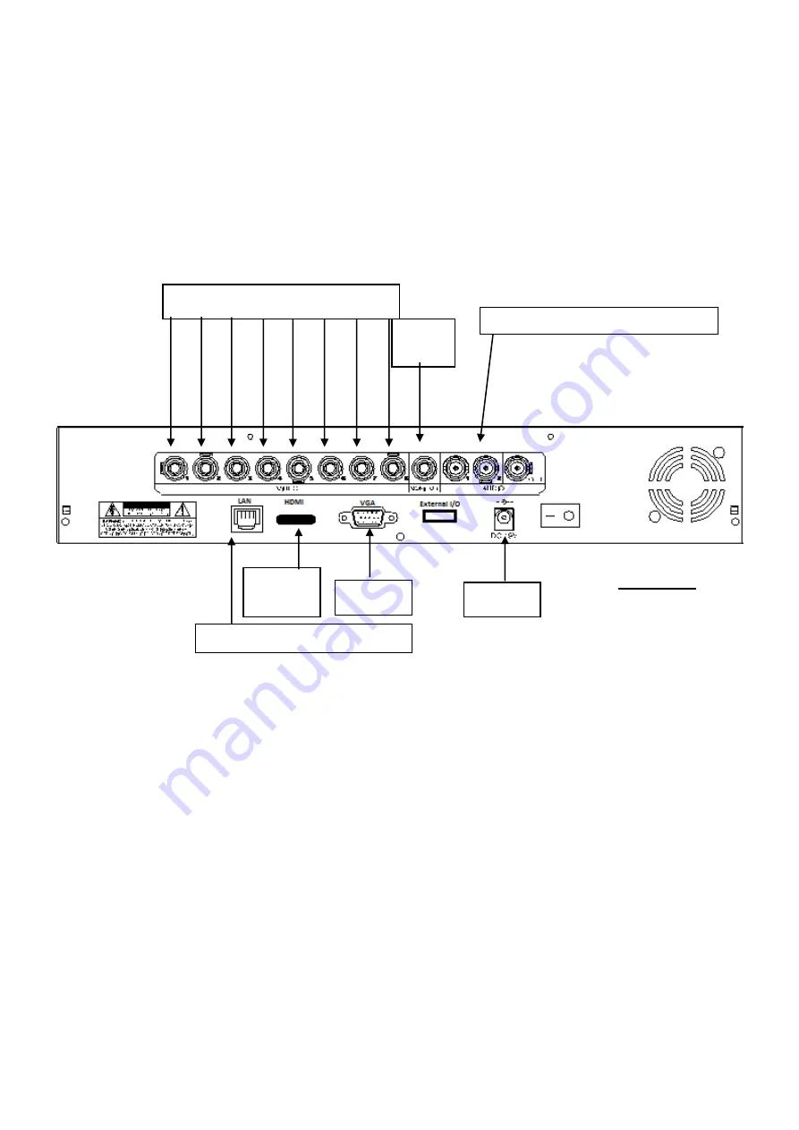
Figure C 

Figure D 

Network cable connection (Optional Use) 

Audio Cable Input(s) and Output (Optional) 

Use) 

Figure E 

HDMI 

Figure A 

Figure 

Installation 

Before installing this unit, please read through the following points: 

  Do not place cords from the AC adapter where they can be pinched or stepped on. 

  Do not place heavy objects on cords, or cover cords with rugs or carpet. 

  Never immerse any component in water, and do not spray cleaners of solvents on the unit. Unplug 

units before cleaning. When cleaning, use a damp, lint-free cloth only. 

  Do not expose the DVR or Cameras to excessive heat, cold, or moisture 


Leave at least a 2” space between the DVR and other objects to allow air circulation around the unit. 

  Service should be handled by qualified technicians. 


Connection Guide 

1. 

Locate the 8 Cameras as required and connect the supplied combination DC Power and Video     

leads. (Yellow to Yellow / Red to Red) 

2. 

Connect the 8 x corresponding camera Video leads (Yellow) into the camera inputs at the rear of 

the DVR (

Figure A

). Be sure to take note of the Camera input 1 

– 8, as this will determine the 

camera channels.   

3. 

Connect the socket end of the 4-way split power cable into one of the plugs on the 5-way cable. 

4. 

Connect the 8 x camera Power leads (RED) into the Power Splitter Cables 

5. 

If you are using a TV/Monitor with Composite Video Input, follow Step 4.1.   

If you are using a TV/Monitor with VGA input, follow Step 4.2 

4.1     Connect the Monitor Connection Cable into the Composite Monitor output on the rear of the 

    DVR (

Figure B

). Connect the Monitor Connection Cable into the RCA Video input on your 

    TV/Monitor (TV/Monitor Not Supplied) 

4.2 

NOTE: VGA is not included. 

Connect the VGA cable to the VGA output or HDMI cable to 

HDMI output on the rear of the DVR (

Figure C & E

). Connect the other end of the VGA cable 

into the TV/Monitor VGA input. 

6. 

Connect the 2Amp 19VDC Power adaptor to the DVR (

Figure D

). 

7. 

Connect the 12VDC Power adaptor to the Power Split Cable. 

WARNING 

Please ensure you use the correct power 

supply for each component.   

DO NOT

 plug the 

19V DVR

 Power supply 

into the cameras as this will damage them

Содержание DVR8ENTPACK3

Страница 1: ...ssion Technology High Quality CCD Image sensor Multiplex Operation 14 x Infrared LEDs Long Recording Duration 520 TVL Resolution Intelligent Video Motion Detection Recording 4 x Indoor Dome Cameras Remote Network Surveillance Backup Functions High Quality CCD Image Sensor Easy to operate with remote or USB mouse 480 TVL Resolution System Auto recovery after power loss blackout N517 www watchguarda...

Страница 2: ...4 x Indoor Dome Cameras For indoor use only 520 TVL resolution Stylish design 8 x Camera Connection Cables Combined DC power and video leads Pre terminated allowing simple plug in connection No tools required 2 x 10m 2x 20m 4 x 30m leads supplied 2 x Power Split Cable 4 way 5 way Allows you to connect all 8 cameras to 1 power supply 1 x Monitor Connection Cable Connect the BNC monitor output from ...

Страница 3: ...s Yellow into the camera inputs at the rear of the DVR Figure A Be sure to take note of the Camera input 1 8 as this will determine the camera channels 3 Connect the socket end of the 4 way split power cable into one of the plugs on the 5 way cable 4 Connect the 8 x camera Power leads RED into the Power Splitter Cables 5 If you are using a TV Monitor with Composite Video Input follow Step 4 1 If y...

Страница 4: ...ld now be displayed on your TV Monitor BEFORE BEGINNING TO RECORD YOU MUST SET the DATE and TIME on your DVR Setting the Date and Time Press MENU on the DVR front panel to bring up the password dialogue box Use the mouse to enter the DVR admin password with the on screen keypad The default admin password is 0000 Users can alter the password later Please refer to the Advanced set up guide CD Press ...

Страница 5: ...se the mouse to enter the DVR password with the password keypad Default administrator password is 0000 The status will be changed from key lock to administrator and the quick menu bar appears on the left side of the screen Password Input Quick Menu Closed Quick Menu Bar Mouse over the arrow mark on the left side of the main screen to extend the quick menu bar and show the five functions as follows...

Страница 6: ...tus display image settings and date time DATE SETUP Click to set the date display and daylight savings SYSTEM Click to set the system configurations EVENT INFORMATION Click to enter the event search menu ADVANCED CONFIG Click to adjust advanced system settings such as recording modes and camera resolutions SCHEDULE SETTING Click to set timer and detection recording ...

Страница 7: ... of 352 x 288 pixels This will provide approximately 16 weeks of recording time on this setting Using Video Motion Detection or reducing image quality can achieve much longer record times if required This unit can be set up to record up to a maximum of 6 25 frames per second per camera in Frame Mode 704 x 576 pixels High Resolution H 264 Compression or 25 frames per second per camera in CIF Mode R...

Страница 8: ...mer indicated by a yellow clock icon in the on screen status bar IMPORTANT NOTE If power is switched off accidentally or in the case of a black out recorded video files will still be stored in the HDD The DVR will return to the original recording status after power is turned on again How to enable motion recording Enter menu go to ADVANCED CONFIG Under DETECTION enable DET for each camera Go to AL...

Страница 9: ...layback PAUSE IMAGE JOG Press II button to pause the current image displayed on the screen In the Pause mode Press once to get one frame forward Press once to get one frame rewind CHANNEL SHIFT Display mode Press MODE button to 4 channels display Full Screen Switch Press 1 2 3 4 buttons to show the full screen channels STOP Pressing button under all circumstances will return DVR to live monitoring...

Страница 10: ...of the DVR to look back though stored data via various events Press LIST button on the front panel of the DVR or the EVENT INFORMATION button on the main menu to enter the search mode Then the screen will show the following window 2006 MAY 12 FRI 15 12 32 CIF Typical Playback Screenshot from DVR The type of recording image size Frame or CIF Play Back Time Time of Actual Event ...

Страница 11: ... the event you d like to view Double click press ENTER to select the footage The DVR will then start playing back the recorded data from the selected event Use the FAST FORWARD REWIND PAUSE SLOW PLAYBACK and CHANNEL SHIFT buttons on the unit or on screen playback control bar to navigate through the footage as required To finish viewing the playback press the stop button to return to the live displ...

Страница 12: ...tons to select the channel to display 11 USB PORT To quickly backup or upgrade firmware OSD you can insert a compatible USB flash drive into the USB port Before using the USB flash drive please use your PC to format the USB flash drive as FAT32 first 12 USB MOUSE PORT Connect a USB mouse to the DVR to provide mouse control 13 UP PAUSE DOWN STOP LEFT REWIND RIGHT FAST FORWARD Press to move the curs...

Страница 13: ...9V 2A is connected to the DVR No recorded video Check if the HDD is installed and connected properly DVR keeps rebooting Ensure that the 12V 3A power supply is connected to the cameras and the 19V 2A is connected to the DVR HDD detection failed Ensure that the 12V 3A power supply is connected to the cameras and the 19V 2A is connected to the DVR Can t detect your USB flash drive Use another USB fl...

Страница 14: ... other basis of liability whatsoever even the loss or damage is caused by its own negligence or fault Seller does not represent that the products it sells may not be compromised or circumvented that the products will prevent any personal injury or property loss by burglary robbery fire or otherwise or that the products will in all cases provide adequate warning or protection Customer understands t...

Страница 15: ...ng possible to ensure that you are happy with your decision and that you have years of satisfaction from your DVR8ENTPACK We take extreme care in the research design and development of our products to ensure they meet your needs Additionally we keep in close contact with our dealers Australia wide and should any problem occur we will work closely with your local dealer to see that it is resolved q...

Отзывы: