background image

40

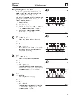
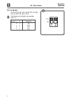
40. Heating

4

Service

Manual

2

3

5205

Programme
unit Al

Card

A21

Heating

elements

Temperature
sensor

Voltage supply

K21

5202

Heating

elements

Voltage supply

K21

K22

Programme
unit A1

Card

A21

Temperature
sensor

Programme
unit A1

Card

A21

5208

Rear control unit

Steam

valve

Y51

Temperature sensor

Fig.

2

Fig.

3

Function

Electric heating

The three heating elements in the machine are
connected to separate phases and are switched
on and off using one or two heating contactors,
K.21 and K22 (two contactors are used for higher
heating power). The heating contactors are
controlled by the programme unit and thermostat
B1.

The programme unit receives information on the
water temperature in the machine from the
thermostat situated in the outer drum. The
programme unit controls the heating contactors
to achieve the set water temperature for the
current washing programme.

When there is no water in the drum, the
programme unit prevents switch-on of the
heating elements. If an error would nevertheless
cause the elements to switch on, a slow-blow
fuse triggers to switch them off again.Then the
heating element has to be changed.

Steam heating

The steam valve is controlled by the programme
unit A1. The control signal goes via the
communication card A21.

Содержание W620 Classic

Страница 1: ...DOC NO 438 9205 85 07 EDITION 49 2004 W620 W630 W640 W655 W675 Classic SERVICE MANUAL ...

Страница 2: ......

Страница 3: ... moving parts and some components that may have sharp edges Improper or careless service procedures may result in serious injury to service personnel REFER SERVICING TO QUALIFIED SERVICE PERSONNEL ABOUT THIS MANUAL This manual is intended to provide service guidance to qualified service personnel Wascomat and its authorized dealers make no determination regarding the qualification of individuals r...

Страница 4: ...Intentionally blank ...

Страница 5: ...MUST BE FOLLOWED DAILY FOR PROPER OPERATION OF YOUR WASCOMAT MACHINE PLEASE ENTER THE FOLLOWING INFORMATION AS IT APPEARS ON THE MACHINE S DATA PLATE S MAKE CERTAIN TO KEEP THIS MANUAL IN A SECURE PLACE FOR FUTURE REFERENCE MACHINE TYPE OR MODEL MACHINE SERIAL NUMBER S ELECTRICAL CHARACTERISTICS ________ VOLTS _______ PHASE _______ HZ ...

Страница 6: ...Intentionally blank ...

Страница 7: ...GN OF THE MACHINE CAUTION 1 Do not attempt to open door unitl Door unlocked indicator is lit 2 Machine must not be used by children 3 Do not use flammable liquids in this machine MACHINE MUST NOT BE USED BY CHILDREN PRECAUCION 1 No intente abrir la puerta hasta que la luz indicadora este encendida 2 La maquina no debe ser operado por ninos 3 No use liquidos inflamable en la lavadora LAS MÁQUINAS N...

Страница 8: ... hot water system that has not been used for 2 weeks or more HYDROGEN GAS IS EXPLOSIVE If the hot water system has not been used for such a period before using a washing machine turn on all hot water faucets and let the water flow from each for several minutes This will release any accumulated hydrogen gas As the gas is flammable do not smoke or use an open flame during this time De l hydrogène pe...

Страница 9: ...ns to start the machine For manually operated models place the ON OFF switch in the ON position and press the Start switch THE MACHINE S MUST NOT START b CLOSE THE DOOR to start machine operation and while it is operating attempt to open the door without exerting extreme force on the door handle The door should remain locked If the machine can start with the door open or can continue to operate wi...

Страница 10: ...Intentionally blank ...

Страница 11: ...rol Thermostat Door and door lock Motor Drain valve Detergent compartment Heating Coin meter Instruction for pulley and replacing bearings 1 2 3 4 5 11 12 21 22 23 24 25 26 27 28 29 30 31 32 33 34 35 36 37 38 39 40 41 42 43 44 45 46 47 48 49 Overview Service instructions Machine components and parts ...

Страница 12: ...Intentionally blank ...

Страница 13: ...1 1 1 Safety precautions Service Manual Contents Safety precautions 3 ...

Страница 14: ...Intentionally blank ...

Страница 15: ...operate the machine Installation and maintenance work should only be done by authorized persons Do not bypass the door lock of the machine Any leaks e g a worn out door seal should be repaired immediately Prior to repairs or maintenance be sure to read the corresponding handbooks and service manuals Do not flush the machine with water ...

Страница 16: ...Intentionally blank ...

Страница 17: ...2 Technical data Contents Technical data 3 Connections 3 ...

Страница 18: ...Intentionally blank ...

Страница 19: ...5 20 20 20 60 60 3 3 3 3 3 75 75 75 75 75 45 45 45 45 45 170 170 170 170 170 DN15 DN15 DN15 DN15 DN15 1 2 1 2 1 2 1 2 1 2 45 90 45 90 45 90 45 90 45 90 300 600 300 600 300 600 300 600 300 600 8 115 8 115 8 115 8 115 8 115 50 800 50 800 50 800 50 800 50 800 Water valves connection Rec water pressure psi kPa Functioning limits psi for water valve kPa Capacity at 45 psi 300 kPa gallon min l min Drain...

Страница 20: ...45 1330 160 1290 245 1125 325 325 100 265 W675 910 1040 1445 500 1075 1155 45 1365 160 1325 245 1155 280 325 100 210 1 Electrical connection 2 Cold water 3 Hot water 4 Steam connection 5 Drain 6 Liquid detergent supply 7 Control panel 8 Soap box 9 Water reuse 10 Door opening W620 ø 310 mm 12 3 16 W630 ø 395 mm 15 9 16 W640 W655 W675 ø 435 mm 17 1 8 A D C 8 10 7 B E N P R F L G I 1 2 3 9 4 5 6 5281...

Страница 21: ...3 4 52 3 8 6 5 16 50 13 16 W675 35 13 16 40 15 16 56 7 8 19 11 16 42 5 16 45 1 2 1 3 4 53 3 4 6 5 16 52 3 16 in inch L M N O P R W620 5 1 8 32 11 16 15 3 16 3 15 16 8 1 4 W630 5 1 8 35 13 16 16 9 16 3 15 16 9 1 4 W640 8 1 4 40 15 1612 13 16 11 5 8 3 15 16 8 7 8 W655 9 5 8 44 5 16 12 13 16 12 13 16 3 15 16 10 7 16 W675 9 5 8 45 1 2 11 12 13 16 3 15 16 8 1 4 A D C 8 10 7 B E N P R F L G I 1 2 3 9 4 ...

Страница 22: ...6 Service Manual Frequency of the dynamic force Hz Max floor load lbs force at extraction kN 9 3 8 7 7 9 8 3 7 5 289 747 410 988 675 1277 530 1133 916 2265 1 2 3 1 1 7 4 1 2 8 5 3 2 2 4 7 3 8 6 0 W620 W630 W640 W655 W675 ...

Страница 23: ... 0 65 16 200 V 3 AC 0 95 10 230 240 V 1 AC 0 75 10 240 V 3 AC 0 95 10 220 V 3 AC 6 6 20 230 V 1 AC 7 2 35 230 V 3 AC 7 2 25 240 V 1 AC 7 8 35 240 V 3 AC 7 8 25 Heating Voltage Total Fuse alternative alternative kW A No heating or Steam heating El heating ...

Страница 24: ... 25 230 V 3 AC 9 6 35 240 V 3 AC 3 4 16 240 V 3 AC 7 9 25 240 V 3 AC 10 4 35 380 V 3N AC 2 9 10 380 V 3N AC 6 3 16 380 V 3N AC 6 7 16 380 V 3N AC 8 8 16 400 V 3 3N AC 3 2 10 400 V 3 3N AC 6 9 16 400 V 3 3N AC 7 3 16 400 V 3 3N AC 9 7 16 415 V 3N AC 3 4 10 415 V 3N AC 7 9 16 415 V 3N AC 10 4 16 440 V 3 AC 10 4 16 Heating Voltage Total Fuse alternative alternative kW A No heating or Steam heating El...

Страница 25: ... 3 25 230 V 3 AC 12 4 50 230 V 3 AC 4 9 20 230 V 3 AC 9 8 35 240 V 3 AC 5 3 20 240 V 3 AC 13 5 50 380 V 3N AC 4 5 10 380 V 3N AC 8 9 16 380 V 3N AC 11 3 20 400 V 3 3N AC 4 9 10 400 V 3 3N AC 9 9 20 400 V 3 3N AC 12 5 25 415 V 3N AC 5 3 10 415 V 3N 13 4 25 440 480 V 13 5 20 Heating Voltage Total Fuse alternative alternative kW A No heating or Steam heating El heating ...

Страница 26: ...3 AC 2 3 10 240 V 1 AC 2 1 16 240 V 3 AC 2 3 10 230 V 3 AC 17 2 50 240 V 3 AC 18 7 50 380 V 3 3N AC 15 7 35 400 V 3 3N AC 17 3 35 415 V 3 3N AC 18 6 35 440 480 V 3 AC 18 7 35 Heating Voltage Total Fuse alternative alternative kW A No heating or Steam heating El heating ...

Страница 27: ...0 230 240 V 3 AC 1 6 10 400 V 3 3N AC 1 4 10 230 V 3 AC 22 63 240 V 3 AC 23 9 63 380 V 3N AC 20 1 35 400 V 3 3N AC 22 2 35 415 V 3 3N AC 23 8 35 440 480 V 3 AC 23 9 35 Heating Voltage Total Fuse alternative alternative kW A No heating or Steam heating El heating ...

Страница 28: ...Intentionally blank ...

Страница 29: ...3 Machine presentation Contents Description 3 General 3 Function 4 General 4 Programme unit 5 Door lock 6 Heating 7 Water connections 7 Rear control unit 7 Detergent compartment 8 Drain valve 8 ...

Страница 30: ...Intentionally blank ...

Страница 31: ...4 6 W630 180 6 4 W640 250 8 8 W655 330 11 7 W675 The machines feature an electromechanical programme unit with fixed washing programmes The machines are supplied to customer specifications with e g electric or steam heating or no heating The machines are designed for installation in hotels laundries such as apartment buildings and coin laundries factories hospitals various institutions etc ...

Страница 32: ...ral overview of the functions of the machine Most functions are then presented in detailed in separate chapters in this service manual Detergent compartment Programme unit Control panel Door Door lock Heating elements Drain valve Frame Outer drum Motor relays Rear control unit Motor Water inlet valves ...

Страница 33: ...mme unit controls the water valves drain valve and heating via the communication card in the rear control unit This unit can also be connected to send control signals to external units for detergent pumps The programme unit of the machine is described in detail in section 23 Programme unit Programme unit Heating element Voltage supply K21 Programme unit A1 Communication card A21 Water valves Drain...

Страница 34: ...lock control can be fitted onto the programme unit This board controls locking and unlocking The card has separate checks for empty drum and stopped drum Together with the checks built into the programme unit this guarantees that the door cannot be opened by a mistake The door lock on the machine is described in detail in section 29 Door and door lock 6 5191 Door lock control A31 Level guard B2 M1...

Страница 35: ... two three or four inlet valves This unit also holds eight connectors for external detergent supply Rear control unit This box contains the main power switch or a connection block for the input voltage heating contactor and a communication card with outputs that control the water and drain valves of the machine as well as the heating There are also connection blocks for connection to e g an extern...

Страница 36: ...ergent The detergent compartment of the machine is described in detail in section 39 Detergent compartment Drain valve This valve is a diaphragm valve that opens and closes by way of the water pressure The control valve is situated next to the water valves The drain valve of the machine is described in detail in section 38 Drain valve Drain valve Detergent compartment 5185 ...

Страница 37: ...11 Regular maintenance Contents Daily 3 Every third month 3 ...

Страница 38: ...Intentionally blank ...

Страница 39: ...k that the drain valve does not leak during the wash cycle Clean out any detergent remaining in the detergent compartment Rapid advance through a program and let the water rinse the compartment Inspect liquid chemical tubing and connections for leaks Repair as necessary Every third month refer this service to qualified personnel May only be carried out by authorized personnel Check that the door d...

Страница 40: ...signs of leakage on the floor beneath the machine Locate and repair any leak On heated machines if the heating time is unusually long check the heating elements see section 40 Heating If the water is very hard check whether there are lime deposits on the heating elements Decalcify the elements if necessary Adapt the amount of deliming agent to the manufacturer s guidelines Never switch on the heat...

Страница 41: ...21 Control unit Contents Description 3 Function 4 Front control unit 4 Program OL02 7 Program OL03 9 Rear control unit 11 ...

Страница 42: ...Intentionally blank ...

Страница 43: ...onnection for received voltage the heat contactor K21 and the communication card A21 with outputs for e g external detergent supply 5925 5182 5916 T1 T2 T3 L1 N N L2 L3 Front control unit Rear control unit Q1 Main power switch K21 Heater contactor A21 Communication card K22 Heater contactor only larger machines X30 X38 X39 X37 X28 X31 X27 X33 X34 X21 X20 X24 X26 X11 X12 X13 X14 X92 X97 X91 X90 X93...

Страница 44: ...ed in detail in section 23 Programme unit Level guard B2 Control of the water level and turning of the drum are controlled with a backup guard to ensure that the door will not open with water in the drum or when the drum rotates Apart from a level guard on the programme unit card there is a level guard B2 connected to the door lock control A31 This card controls door locking action as well as the ...

Страница 45: ... after selected temperature is reached Note The pump signal on connection X72 5 will appear 30 seconds before the flushing of compartment 4 Jumper on D is main wash function It is recommended when compartment 4 is used for main wash detergent or if main wash detergent is supplied from pump Jumper on F gives a correct function of valve Y12 W3180 3330N W640 675 There are no Y22 valve on these machin...

Страница 46: ...rogram OG01 I H F D C B A TERMOSTAT X23 X36 X35 X191 WATER NO HEAT NO Y22 NO Y35 BLEACH SMALL DET 2 BIG 1 2 3 4 5 6 BOX4 Y25 Y35 Y25 Y22 Y14 Y15 Y13 Y12 Y11 1 2 3 4 5 6 1 2 1 2 K21 Y51 1 2 3 4 5 6 7 1 2 3 4 5 1 2 3 4 1 2 3 4 5 6 1 2 X391 X111 X112 X114 X113 NO Y25 G 3 1 2 X291 7 5 6 7 6 7 P1 ...

Страница 47: ...from pump Jumper on E gives a correct function of valve Y15 cold water The valve Y15 will open in main wash W3180 3330N W640 675 Jumper on F gives a correct function of valve Y12 W3180 3330N W640 675 There are no Y22 valve on these machines Jumper on G W3180 3330N W640 675 with only cold water inlet The signal for Y25 hot inlet will give cold inlet Y15 instead Jumper on H for the machines W3180 33...

Страница 48: ...3 X36 POWER OUT NO Y25 BLEACH SMALL DET 2 BIG 1 2 3 4 5 6 Y25 Y35 Y25 Y22 Y14 Y15 Y13 Y12 Y11 1 2 3 4 5 6 1 2 K21 1 2 3 4 5 6 7 1 2 3 4 5 1 2 3 4 1 2 3 4 5 6 1 2 X111 X112 X113 X114 X291 1 2 G E Y15 D C BOX4 H I J NO Y35 NO Y22 NO HEAT NO TIME EXT BIG X191 P2 7 6 7 5 6 7 1 2 X391 POWER IN X35 3 ...

Страница 49: ...pump unit There will be a flushing in compartment 4 during 30 seconds 3 5 minutes after selected temperature is reached Note The pump signal on connection X72 5 will appear 30 seconds before the flushing of compartment 4 Jumper on D is main wash function It is recommended when compartment 4 is used for main wash detergent of if main wash detergent is supplied from pump Jumper on E gives correct fu...

Страница 50: ... press Cold Frio Warm Templado Hot Caliente extract centrifugado soak pre la v a d o Program OL03 F X161 X36 1 2 3 4 5 6 1 2 3 4 5 6 7 8 1 2 3 4 5 6 7 1 2 3 4 5 1 2 3 4 1 2 3 4 5 6 X111 X112 X113 X114 D C P03 E B A 1 2 3 4 X160 OPTIONS OPTIONS DISTRIB CARD DET 2 BOX4 BLEACH BOX4 Y25 SMALL Y15 BIG Y25 BIG 7 6 7 5 6 7 NO Y22 ...

Страница 51: ...e 0 position The received voltage supply is connected to the lower screw post of the main power switch alt the terminal connection Heating contactor K21 This contactor is only featured on machines with electric heating It activates the three heating elements at the front lower part of the outer drum It is controlled by the programme unit A1 and thermostat B1 Heating contactor K22 This contactor is...

Страница 52: ...tion blocks Control signals for connection to external system such as detergent supply Card No Function Outputs 110V AC X70 see Payment system X71 1 0 V Door locked common X71 2 L1 Door locked X72 1 Common X72 2 Liquid supply 1 Pre wash X72 3 Liquid supply 2 Main wash X72 4 Liquid supply 3 Softener X72 5 Liquid supply 4 Bleach Fig 8 Fig 9 9 6052 Card A X53 X52 X51 X50 X41 X42 X43 X44 X45 X46 X72 X...

Страница 53: ...tion card is only available on machines with programme OL03 10 T1 T2 T3 L1 N N L2 L3 Option card 5182 5475 wash la v a d o r i n s e a c l a r a d o Delicato Prendas delicadas Perm press Cold Frio Warm Templado Hot Caliente extract centrifugado soak pre la v a d o ...

Страница 54: ...bilities to alter the standard parameters in the wash programs by moving or adding jumpers on the option card When adding a jumper on N or M gives warm rinses instead of cold M shall be used on W375 W3130N W620 630 and N on W3180N W3330N and W640 675 3 spare jumpers Fig 11 Fig 12 ...

Страница 55: ...timer rapid advances the prewash automatically Remember that Delicate is always without prewash When adding a jumper on P there will be two rinses instead of three The timer rapid advances the first rinse If the jumper on Q is removed the main wash will be extended by three minutes to nine minutes instead of six Fig 13 Fig 14 Fig 15 ...

Страница 56: ...ontrol unit 16 Service Manual 16 5606 In standard position on R low level is used in prewash main wash and high level in rinses If jumper is moved to S it will be high level also in prewash and mainwash Fig 16 ...

Страница 57: ...26 Level control Contents Control and fault tracing 3 Water level check 4 Water level is too high 4 ...

Страница 58: ...Intentionally blank ...

Страница 59: ...back to original position but now at lower water levels than was required to activate the contacts when the drum was being filled These levels are called minimum levels If the water level during washing falls below the minimum level water will be added until the shut off level is again reached Control and fault tracing All level sensors are factory set for the various machines As a rule this setti...

Страница 60: ... high water level for rinsing Water level is too high Check that the hose connecting the level switch and the drain valve is not obstructed When necessary and when the machine is empty of water clean the hose by disconnecting it from the level switch and blowing air through it Check the hose for holes which can be caused by the hose rubbing against the pulley Overfilling can also be caused by burn...

Страница 61: ...27 Thermostat Contents Data 3 Description 3 Repair instructions 4 Replacing the thermostat 4 ...

Страница 62: ...Intentionally blank ...

Страница 63: ...t sensor is located at the lowest point of the outer drum to the left of the heating element A liquid filled cable capillary tube runs from the sensor to the thermostat located in the automatic control unit The water temperature controls the liquid expansion and thereby the activation of the various thermostat contacts Temperature selection contact selection 90 C 60 C 40 C or 30 C is controlled by...

Страница 64: ...changed For that reason the thermostats are sealed with enamel paint The machine guarantee ceases to be valid if the thermostat is tampered with Replacing the thermostat Remove the front panel and pull out the thermostat sensor Undo the capillary tube strapping and replace the thermostat Install the new capillary tube in the same way as the old one ...

Страница 65: ...escription 3 General 3 Function 4 The door lock locks the door 4 The door lock unlocks the door 5 Error codes 6 Reset button 7 Door lock control inputs outputs 7 Repairs 10 Emergency opening of door lock 10 Replacing the door lock 11 ...

Страница 66: ...Intentionally blank ...

Страница 67: ... is closed when the door is closed An emergency opening arm emergency opening button that can be used to open the door lock in an emergency Door lock controller A31 situated in the front control unit of the machine This card controls the door lock function and supervises whether the drum is empty and not turning It locks and unlocks the door lock when the programme unit requests door locking or un...

Страница 68: ...lses on input X95 from rotation sensor B3 When the above conditions are met the card A31 outputs a closing pulse on output X96 to the door lock actuator coil which then locks the door The micro switches S4a and S4b in the actuator door lock are closed when the door is locked These micro switches feed voltage to The output switches on the programme unit The switches control the machine s drain and ...

Страница 69: ...m motor controller A107 open 5 V Drum not turning no pulses on input X95 from rotation sensor B3 When the above conditions are met the door lock controller outputs an opening pulse on output 96 to the door lock actuator coil which then unlocks the door Micro switches S4a and S4b now interrupt the relays switches The drain water valves heater and motor cannot now be switched on Door lock control A3...

Страница 70: ...unlocked LEDs Normal operation A B C No error The drum is not turning LEDs blinking No error The drum is rotating LEDs Error state A B C Level guard B2 indicates water in drum when the door lock is open input X93 not closed Motor control indicates that motor is operating when door lock is open input X94 not open No signal from rotation sensor B3 frequency input X95 0 4 Hz in spite of the motor con...

Страница 71: ...to programme unit A1 X92 Input from programme unit Lock door Prior to the door lock control locking the door output X96 a check is made for any water left in the drum input X93 closed and whether the drum is not rotating input X94 open Input voltage X96 Function 110 240 V AC Programme unit requests door locking 0 V Programme unit requests door opening 5193 Door lock control A31 X90 X91 1 2 1 2 200...

Страница 72: ...d The LEDs then show the error code The input signal from X94 is compared with the signal from the rotation sensor B3 input X95 If the motor signal is operating but the rotation sensor does not provide a signal the error code is shown If the rotation sensor indicates motor rotation when there is no motor signal the error code is shown Input voltage Function X94 5 V DC Motor not operating input clo...

Страница 73: ...e following conditions are met DC 110 240 V AC on input X92 programme unit requests door locking DC 0 V on input X93 no water in drum DC 5 V on input X94 motor not operating No pulses on input X95 drum not rotating No error code present Unlocks the door lock when the following conditions are met DC 0 V on input X92 programme unit requests door unlocking DC 0 V on input X93 no water in drum DC 5 V ...

Страница 74: ... machine by turning the main power switch to the 0 position 2 Remove the front cover or top cover When replacing the door lock it is recommended to remove the front cover 3 Pull the emergency opening arm to the side This retracts the spring loaded locking pin and the door lock opens Alt Press down the emergency opening button 4 Reset the emergency opening correctly Fig 10 5369 6111 10 ...

Страница 75: ...ve the door two screws in each hinge 4 Remove the front panel 5 Remove the door lock three holding screws 6 Verify the strap positions on the cable for the lock Cut the necessary straps to undo the cables leading to the lock 7 Undo the connectors 8 Replace the door lock 9 Reconnect the new door lock 10 Assemble in reverse order 11 Strap the cables for the lock according to the notes made in step 6...

Страница 76: ...Intentionally blank ...

Страница 77: ...30 Motor Contents Warnings 3 Description 4 Motor 4 Principle wiring 5 Motor overload protector 6 Repairs 7 Motor replacement 7 Adjustments 8 Drive belt tension 8 ...

Страница 78: ...Intentionally blank ...

Страница 79: ...3 30 30 Motor Service Manual Warnings DANGER Be careful when measuring capacitors and filter ...

Страница 80: ...ed by contactors The motor winding is protected against overloads using a thermal overheating protector that is automatically reset The motor is connected directly to the motor module via a cable with quick connectors 5467 5465 Motor Rotation sensor B3 2 5975 Programme unit A1 Rotation control card A31 X24 X94 X97 X95 B3 Motor Contactors A107 1 or 3 phase Thermal protection X27 X26 ...

Страница 81: ... 6 C3 6 Aux Main Wash speed 18 pole Extract speed 2 pole A Only machines with start switch Note Some machines may hav overcurrent protection This is not shown here A Principle wiring 4 3 6 5 2 1 4 3 6 5 2 1 K1 K2 Black Blue White Black Blue White 4 3 6 5 2 1 K4 Note Some motors are possible to change from Y to D connection to accomodate different voltages ...

Страница 82: ...rs are connected in series and will trip at a temperature of 150 5 C A burned out motor can be re wound Some single phase machines are also equipped with a manual resettable overload protector mounted on the extract relay in the motor module This overload protector protects the motor during the start up of the extraction 4 0304 Fig 4 ...

Страница 83: ...ower rear piece then remove the rear cover 4 Undo the ground connection from the motor 5 Remove the drive belt by pulling the belt towards you while rotating the drum by hand 6 Undo the motor cable from motor 7 Undo and remove the motor mounting bolts 8 Lift out the motor Assembly 1 Fit the new motor without locking the mounting bolts 2 Fit the drive belt and adjust the belt tension with the tensi...

Страница 84: ...that the motor operates normally Adjustments Drive belt tension The drive belt is pre tensioned upon delivery from the factory The drive belt tension should be as follows Model Force A Post tensioning B New belt C N mm mm W375N 35 8 6 W385N 35 9 8 W3105N 40 8 7 W3130N 40 8 7 W3180N 60 9 7 W3250N 68 8 7 W3330N 45 8 6 To adjust drive belt tension first undo the motor retaining screw a couple of turn...

Страница 85: ...38 Drain valve Contents Description 3 Function 3 Repairs 4 Disassembly 4 Assembling 5 ...

Страница 86: ...Intentionally blank ...

Страница 87: ...s connected to the lower part of the drain valve When the lower part is filled with water the lower part diaphragm pushes up the piston The piston lifts the pressure plate against the drain valve rubber diaphragm which in turn forms a seal against the outer drum effectively closing the valve When the drain valve should be opened the control valve changes position to allow the water pressure to the...

Страница 88: ... the drain hose from upper part of the valve 4 Undo the hose clamp holding the valve rubber bellows against the sleeve coupling of the outer drum 5 Loosen and unscrew the 4 retaining nuts of the valve a couple of turns use a socket extender and ratchet wrench Turn the valve and unhook it from the bolts 6 Disconnect the pressure hose from the lower part of the valve 7 Replace the valve with a new o...

Страница 89: ... 3 Hook the valve onto the bolts and turn the valve into position Secure the 4 retaining bolts of the valve 4 Secure the hose clamp at the connection of the rubber bellows on the sleeve coupling 5 Connect the drain hose to the upper part of the valve 6 Turn the main power switch to position 1 and verify correct valve operation and that it does not leak 7 Reattach the front cover Fig 4 Fig 5 Fig 3 ...

Страница 90: ...Intentionally blank ...

Страница 91: ...39 Detergent compartment Contents Description 3 ...

Страница 92: ...Intentionally blank ...

Страница 93: ...ch have one connector while compartments 1 and 2 each have two connectors one for cold water the other for warm water The detergent is routed from the bottom of the compartment to the outer drum through the combo module immediately behind the compartment To safeguard against overfilling e g due to a blocked hose on its way to the drum the combo module features an overflow drain directly connected ...

Страница 94: ...Intentionally blank ...

Страница 95: ...40 Heating Contents Description 3 Electric heating 3 Function 4 Electric heating 4 Steam heating 4 Repairs 5 Replacing the heating elements 5 ...

Страница 96: ...Intentionally blank ...

Страница 97: ...sor are situated at the bottom of the outer drum close to the edge They can be accessed front the front after the front plate is removed The contactor s is are placed in the rear control unit Depending on the size of the machine the following heating elements are available Machine Heating element size model kW W375N 3x0 665 3x1 3x1 8 3x2 5 W385N W620 3x0 665 3x1 3x1 8 3x2 5 W3105N 3 x 3 3 W3130N W...

Страница 98: ...er heating power The heating contactors are controlled by the programme unit and thermostat B1 The programme unit receives information on the water temperature in the machine from the thermostat situated in the outer drum The programme unit controls the heating contactors to achieve the set water temperature for the current washing programme When there is no water in the drum the programme unit pr...

Страница 99: ...e by turning the main power switch to the 0 position 2 Remove the front cover 3 Make a note of how the heating elements are connected 4 Disconnect the connection to the heating element to be replaced 5 Unscrew the nut between the connections approx 1 cm 6 Push on the nut and bolt to undo the expansion bracket from the outer drum 7 Remove the old heating element and install the new one Be sure that...

Страница 100: ...Intentionally blank ...

Страница 101: ...41 Coin meter Contents Price programming 3 Setting wash price 3 Programming the current price 5 Price reduction 6 ...

Страница 102: ...Intentionally blank ...

Страница 103: ...nd 2 if the coin meter has two slots If only one coin all switches shall be set in OFF position 2 is the switch S2 for setting the price 3 is the switch S3 for price reduction 4 is coin one input for coin sensor one 5 is coin two input for coin sensor two 6 Yellow LED flashes with frequency 3 Hz the value left to insert and indicates accepted coin lit 1 second 7 Green LED flashes relation coin 1 a...

Страница 104: ... coin all switches shall be placed in OFF position The following combination is available ON 1 Switch 1 2 3 4 Ratio 0 0 0 0 1 1 1 0 0 0 1 2 0 1 0 0 1 4 1 1 0 0 1 5 0 0 1 0 1 10 1 0 1 0 1 20 0 1 1 0 2 5 Example Ratio 1 2 Value 2 is twice the value of 1 Ratio 1 4 Value 4 is four times the value of 1 Ratio 2 5 Value 5 is two and half times the value of 2 Fig 2 ...

Страница 105: ...gle coin insertion A is always 1 V value of coin When counter unit is for double slot the lower value Ex 1 P 2 EURO 50 cent Ratio 1 2 1 EURO and 50 cent coins A 1 V 50 I 250 x 1 50 5 The switch should be set to 5 which can be achieved by setting switches 1 and 3 in position ON 1 4 5 Ex 2 P 1 EURO 50 cent Ratio 2 5 10 cent and 25 cent coins A 2 V 10 I 150 x 2 10 30 The switch should be set to 30 wh...

Страница 106: ...vice Manual 5 5722 OFF ON 1 2 Price reduction If one want to have price reduction for a certain day etc switch S3 can be used The following combinations are possible ON 1 Switch 1 2 Reduction 0 0 0 1 0 25 0 1 50 1 1 75 Fig 5 ...

Страница 107: ...42 Instruction for pulley and replacing bearings Instruktion för remskiva Instruction for pulley W365H N M W3330H N M EX618 EX670 E W SU620 675 438 9041 53 04 21 ...

Страница 108: ...Intentionally blank ...

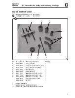
Страница 109: ...uller 1 2 432 1728 01 Avdragare remskiva Pulley drag 2 3 432 1717 01 Adaptor Adaptor G1 2 M10 1 4 432 1720 01 Bricka Washer 1 5 438 6031 02 Mutter Nut G 1 2 1 6 432 1721 01 Hylsa Sleeve 48 x 42 L 80 1 7 432 1721 02 Hylsa Sleeve 60 x 54 L 90 1 8 432 1721 03 Hylsa Sleeve 75 x 69 L 100 1 438 8002 02 Gängtapp Thread tap M12 1 438 8001 02 Borr Drill 1 For W365 385H N M For W3105H N 3130H N M 3180N M Fo...

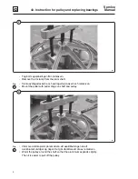
Страница 110: ...avdragsklackarna och avdragarna på axeln och remskivan Mount the puller with puller drags on shaft and pulley 3 337 Värm med värmepistol på remskivan vid axelinfästningen så att aluminiumet utvidgar sig något Det går då lättare att dra av remskivan Warm the pulley around the shaft so that the aluminium expands slightly Then it is easier to pull off the pulley Fig 3 ...

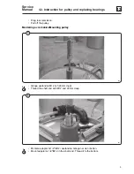
Страница 111: ...an M12 och 20 mm djupt Thread the shaft end with M12 and 20 mm deep 5 367 Montera adapter G 1 2 M12 i axeländan Gänga ner den i botten Mount adaptor G 1 2 M12 in the shaft end Thread it to the bottom Fig 5 Montering av remskiva Mounting pulley 4 362 Drag loss remskivan Pull off the pulley ...

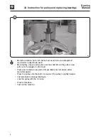
Страница 112: ...xeln Mount pulley sleeve and washer over the shaft Mount the puller screw with nut in the adaptor on the shaft Pressa ner remskivan på axeln Det går lättare om remskivan värms med värmepistol Press the pulley onto the shaft It is easier if the pulley is slightly heated Lås remskivan med segersäkringen Lock the pulley with the C clamp Provkör maskinen Test run the machine ...

Страница 113: ...42 Instruction for pulley and replacing bearings Instruktion för lagerbyte Instruction for replacing bearings W365H N M W3330H N M EX618 EX670 E W620 675 438 9041 61 02 04 21 ...

Страница 114: ...Intentionally blank ...

Страница 115: ...630 1 5 432 1716 03 Distans Spacer W3130H W3180N M EX630 E W640 1 6 432 1716 04 Distans Spacer W3180 3300H W3250 3330N M EX640 670 E W655 675 1 7 432 1719 01 Dorn stora lagret Drift large bearing W365 385H N M EX618 E W620 1 8 432 1719 02 Dorn stora lagret Drift large bearing 1 W3105H N M W3130N M EX625 E W630 9 432 1719 03 Dorn stora lagret Drift large bearing 1 W3130H W3180N M EX630 E W640 10 43...

Страница 116: ...g 2 Avmontering av remskiva se instruktion 438 9041 53 Removal of pulley see instruction 438 9041 53 Tag bort kilen från axeln Remove wedge from shaft Mät avståndet A mellan lager och axelända Measure the distance A between bearing and end of shaft Axel Shaft A Lager Bearing ...

Страница 117: ...cing bearings Fig 3 Skruva loss bultarna i lagerhuset Loosen the bolts in the bearing house 4 339 Montera två bultar i lagerhusets gängade hål och pressa loss lagerhuset Mount two bolts in threaded holes and press until the bearing house is loose Fig 4 3 338 ...

Страница 118: ... ej dra av bakgaveln när det främre lagret sitter kvar då förstörs klädselplåten If the front bearing is still on the shaft use the puller to remove it In order to be able to put the puller blocks under the bearing push the rear gable a little Do not attempt to remove the rear gable when the bearing is still on the shaft It will result in a damaged lining Tag bort tätningarna och därefter bakgavel...

Страница 119: ...gen på tre ställen ca 120 mellan Ibland räcker det för att den skall släppa Alt 1 Tap the bushing in three places with about 120 in between Sometimes it is sufficient to loosen it from the shaft Alt 2 Mejsla eller slipa bort bussningen från axeln Alt 2 Chisel or grind the bushing off the shaft 6 346 ...

Страница 120: ...e Manual 42 42 Instruction for pulley and replacing bearings 14 Fig 7 Knacka ur lagren ur lagerhuset Tap the bearings from the bearing house Rengör lagerhuset noggrant Clean the bearing house thoroughly 7 347 ...

Страница 121: ... W365H W375H N W385N M EX618 E W620 472 9913 12 W3105H N M W3130N M EX625 E W630 472 9913 13 W3250N M E W655 472 9913 15 W3180N M E W640 472 9913 14 W3330N E W675 472 9913 19 W3330N M 472 9913 16 Lagersats Bearing kit W3130H EX630 472 9913 17 W3180H EX640 472 9913 18 W3240H EX655 472 9913 19 W3300H EX670 472 9913 64 ...

Страница 122: ... 10 Fyll främre lagret med fett och knacka försiktigt ner lagerhuset med hjälp av dorn och bricka Fill the front bearing with grease and tap it gently into the housing with drift and washer 11 350 Fyll lite fett i lagerhuset Put some grease into the housing Fig 11 10 348 349 ...

Страница 123: ...erhuset och knacka försiktigt ned det bakre lagret med hjälp av pressdornet Turn the housing around and gently tap the rear bearing into the housing using the presser 13 Montering av tätningsringar Mounting of sealings Fig 13 12 351 352 Lagerhus Bearing housing Tätningsringar Sealing rings ...

Страница 124: ... for pulley and replacing bearings 18 Fig 14 Smörj lagerhusets innersida med lite fett så går det lättare att montera tätningarna Put some grease on the inside of the bearing housing Then it is easier to mount the sealing rings 14 354 ...

Страница 125: ...ett Fill the first sealing with grease Placera tätningen på dornet med tätningens öppning uppåt Knacka försiktigt ned den i lagerhuset Tätningen skall ned tills det tar stopp Place the sealing on the drift with the opening up Tap carefully it down in the bearing housing Push it down until it stops 15 353 355 ...

Страница 126: ... Fig 16 Fyll den andra tätningen med Amblygon fett Placera distansring och tätning på dornet Pressa ner dornet i botten på lagerhuset Fill the second sealing with Amblygon grease Place the spacer and sealing on the drift Press down the drift to the bottom 16 356 357 359 ...

Страница 127: ...d replacing bearings Fig 17 Montera den tredje tätningen Läppen skall ligga an mot lagerhuset Tryck ej för långt tätningsläppen kan gå sönder Mount the third sealing The lip shall lay against the housing Don t push too far as the lip can break 17 361 ...

Страница 128: ...nd nipple are OK If not replace Gänga axeländan med M10 och min 20 mm djupt Thread the shaft end with M10 and min 20 mm deep 19 364 Montera lagerhuset på bakgaveln och korsdrag bultarna OBS Markering Up på lagerhuset skall peka upp när bakgavel är monterat på maskinen Mount the bearing housing to the rear gable and tighten the bolt crosswise NOTE The marking Up shall be pointing up when rear gable...

Страница 129: ...d on the shaft Montera adapter på axeländan och skruva ner den i botten Mount the adaptor on the shaft end and thread it down to the bottom 21 366 Montera pressdorn bricka mutter och avdragarbult Pressa ner gaveln i botten Kontrollera måttet mellan axelända och bakre lagerbana som uppmättes vid isärtagningen Mount presser washer nut and puller bolt Press down the rear gable until stop Check the me...

Страница 130: ...n Pressa ned remskivan på axeln Det går lättare om remskivan värms Mount pulley sleeve washer nut and puller bolt onto the shaft Thread the bolt to the adaptor on the shaft Press the pulley onto the shaft It is easier if the pulley is heated 23 369 Lås remskivan med segersäkringen Lock the pulley with the C clamp Byt tätningen runt bakgavelns ytterkant Replace the gasket around the circumference o...

Страница 131: ...rumpaketet i yttertrumman OBS Texten Up på bakgaveln skall peka uppåt Lift the drum package into the outer drum NOTE The text Up on the rear gable must be pointing upwards Återmontera övriga detaljer Remount other parts in their proper places Provkör maskinen Test run the machine ...

Страница 132: ......

Отзывы: