


●
To enhance the temperature control of the LT water, by increasing the seawater temperature
9.3.1
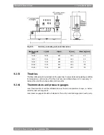
Stand-by circulation pumps (4P03, 4P05)
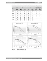
Stand-by pumps should be of centrifugal type and electrically driven. Required capacities and
delivery pressures are stated in Technical data.
NOTE
Some classification societies require that spare pumps are carried onboard even
though the ship has multiple engines. Stand-by pumps can in such case be worth
considering also for this type of application.
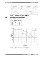
9.3.2
Sea water pump (4P11)
The capacity of electrically driven sea water pumps is determined by the type of coolers and
the amount of heat to be dissipated.
Significant energy savings can be achieved in most installations with frequency control of
electrically driven sea water pumps. Minimum flow velocity (fouling) and maximum sea water
temperature (salt deposits) are however issues to consider.
9.3.3
Temperature control valve for central cooler (4V08)
When it is desired to utilize the engine driven LT-pump for cooling of external equipment, e.g.
a reduction or a generator, there must be a common LT temperature control valve in the
external system, instead of an individual valve for each engine. The common LT temperature
control valve is installed after the central cooler and controls the temperature of the water
before the engine and the external equipment, by partly bypassing the central cooler. The
valve can be either direct acting or electrically actuated.
The set-point of the temperature control valve 4V08 is 38 ºC in the type of system described
above.
Engines operating on HFO must have individual LT temperature control valves. A separate
pump is required for the external equipment in such case, and the set-point of 4V08 can be
lower than 38 ºC if necessary.
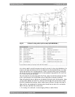
When there is no temperature control valve in the seawater system (4V07, see figure 9.16), it
is advised to install a temperature control valve over the central cooler(s) in order to maintain
the temperature before engine at a constant value.
9.3.4
Temperature control valve for heat recovery (4V02)
The temperature control valve after the heat recovery controls the maximum temperature of
the water that is mixed with HT water from the engine outlet before the HT pump. The control
valve can be either self-actuated or electrically actuated.
The set-point is usually somewhere close to 75 ºC.
The arrangement shown in the example system diagrams also results in a smaller flow through
the central cooler, compared to a system where the HT and LT circuits are connected in parallel
to the cooler.
9.3.5
Coolers for other equipment and MDF coolers
The engine driven LT circulating pump can supply cooling water to one or two small coolers
installed in parallel to the engine, for example a MDF cooler or a reduction gear cooler. This
is only possible for engines operating on MDF, because the LT temperature control valve
cannot be built on the engine to control the temperature after the engine. Separate circulating
pumps are required for larger flows.
Design guidelines for the MDF cooler are given in chapter Fuel system.
9-10
Wärtsilä 26 Product Guide - a9 - 7 September 2016
Wärtsilä 26 Product Guide
9. Cooling Water System
Содержание WARTSILA 26
Страница 1: ...W RTSIL 26 PRODUCT GUIDE...
Страница 12: ...This page intentionally left blank...
Страница 34: ...This page intentionally left blank...
Страница 50: ...This page intentionally left blank...
Страница 92: ...This page intentionally left blank...
Страница 114: ...This page intentionally left blank...
Страница 148: ...This page intentionally left blank...
Страница 160: ...This page intentionally left blank...
Страница 172: ...This page intentionally left blank...
Страница 182: ...This page intentionally left blank...
Страница 188: ...This page intentionally left blank...
Страница 190: ...This page intentionally left blank...
Страница 193: ......
Страница 194: ......
Страница 195: ......


