background image

s1fmdl1sm-REV1207 

Model S1F Metallic Page 13

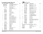
ITEM 

PART  NUMBER 

DESCRIPTION 

QTY

  1 

031-140-001 

Air Valve Assembly (Cast Iron Centers Only) 


031-146-000 

Air Valve Assembly (Stroke Indicator) 

1

             031-147-000 

Air Valve Assembly(Stroke Indicator) 


031-183-000 

Air Valve Assembly   

1


031-183-001 

Air Valve Assembly


(W/ Stainless Steel Hardware) 

1


031-173-000 

Air Valve Assembly 


(W/ Aluminum centers only) 

1


031-173-001 

Air Valve Assembly


(W/ Stainless Steel Hardware only) 

1

  2 

050-028-354 

Ball, Check 


050-028-360 

Ball, Check 

4


05`0-028-365 

Ball, Check 

4


050-028-600 

Ball, Check 

4

  3 

070-012-170 

Bushing 

2

  4 

095-110-000 

Pilot Valve Assembly  

1


095-110-558 

Pilot Valve Assembly  

1


(Cast Iron Centers Only)

  5 

114-025-157 

Intermediate  

1


114-025-010 

Intermediate 

1

  6 

132-019-360 

Bumper 

2

  7 

135-036-506 

Bushing 

2

  8 

165-120-157 

Cap, Air Inlet Assembly 

1


165-120-010 

Cap, Air Inlet Assembly 

1

  9 

170-044-115 

Capscrew, Hex Hd 5/16-18 X 1.00 

16


170-044-330 

Capscrew, Hex Hd 5/16-18 X 1.00 

16

  10 

170-045-115 

Capscrew, Hex Hd 5/16-18 X 1.25 

16


170-045-330 

Capscrew, Hex Hd 5/16-18 X 1.25 

16

  11 

170-069-115 

Capscrew, Hex Hd 5/16-18 X 1.75 

4


170-069-330 

Capscrew, Hex Hd 5/16-18 X 1.75 

4

  12 

171-053-115 

Capscrew, Hex Soc 3/8-16 X 2.50 

4


(Stroke Indicator option only)


171-053-330 

Capscrew, Hex Soc 3/8-16 X 2.50 

4


(Stroke Indicator option only)


170-006-115 

Capscrew, Hex HD 3/8-16 X 1.00 


170-006-330 

Capscrew, Hex HD 3/8-16 X 1.00 

4

  13 

196-173-156/157 

Chamber, Outer 

2


196-173-010 

Chamber, Outer 

2


196-173-110 

Chamber, Outer 

2

  14 

286-008-354 

Diaphragm 

2


286-008-360 

Diaphragm 

2


286-008-363 

Diaphragm 

2


286-008-364 

Diaphragm 

2


286-008-365 

Diaphragm 


286-112-000 

Diaphragm, One-Piece Bonded 

2

  15 

286-015-604 

Diaphragm, Overlay 

2

  16 

360-093-360 

Gasket, Air Valve 

1

  17 

360-103-360 

Gasket, Pilot Valve 

1

  18 

360-104-379 

Gasket, Air Inlet Cap 

1

  19 

518-175-156 

Manifold, Suction 

1

Composite Repair Parts List


518-175-156E 

Manifold, Suction 1" BSP Tapered 

1


518-175-010 

Manifold, Suction 

1


518-175-010E 

Manifold, Suction 1" BSP Tapered 

1


518-175-110 

Manifold, Suction 

1


518-175-110E 

Manifold, Suction 1" BSP Tapered 

1

  20 

518-176-156 

Manifold, Discharge 

1


518-176-156E  

Manifold, Discharge 1" BSP Tapered 

1


518-176-010 

Manifold, Discharge 

1


518-176-010E 

Manifold, Discharge 1" BSP Tapered 

1


518-176-110 

Manifold, Discharge 

1


518-176-110E 

Manifold, Discharge 1" BSP Tapered 

1

  21 

560-001-360 

O-Ring 

  22 

560-091-360 

Seal (Check Valve) (See item 29) 


560-091-363 

Seal (Check Valve) (See item 29) 

8


560-091-364 

Seal (Check Valve) (See item 29) 


560-091-365 

Seal (Check Valve) (See item 29) 

8


560-091-611 

Seal (Check Valve) (See item 29) 

8

  23 

612-022-330 

Plate, Inner Diaphragm  

2


612-218-330 

Plate, Inner Diaphragm  


(use with One-Piece Bonded)

  24 

612-108-157 

Plate, Outer Diaphragm Assembly 

2


612-101-082 

Plate, Outer Diaphragm Assembly 

2


612-101-110 

Plate, Outer Diaphragm Assembly 

2

  25 

620-022-115 

Pin, Actuator 

2

  26 

675-042-115 

Ring, Retaining 

2

  27 

685-060-120 

Rod, Diaphragm 

1

  28 

720-010-375 

Seal, U-Cup 

2

  29 

722-098-550 

Seat, Check Ball 

4


722-098-080 

Seat, Check Ball (seals required see item 22) 

4


722-098-110 

Seat, Check Ball (seals required see item 22) 

4


722-098-150 

Seat, Check Ball (seals required see item 22) 

4


722-098-600 

Seat, Check Ball 

4

  30 

900-004-330 

Lock Washer, 5/16 

16


900-004-115 

Lock Washer, 5/16 

16

  31 

901-038-330  

Flat Washer, 5/16 


901-038-115 

Flat Washer, 5/16 

4

  32 

530-033-000 

Muffler, Metal 

1

Parts not shown used with Raised Face Flange Porting Option

170-044-330 

Hex Cap Screw 

4

326-050-080 

Mounting Bracket 

2

334-112-110 

1" Raised Face, 150# ANSI Flange 

2

538-035-110 

Pipe Nipple 1" NPT x 1½" 

2

545-004-330 

Hex Nut 

4

900-004-330 

Lock Washer 

4

901-009-330 

Flat Washer 

8

I M2 c T5
II 2GD T5

ATEX Compliant

ITEM 

PART  NUMBER 

DESCRIPTION 

QTY

Содержание SANDPIPER S1FB1A1WANS000

Страница 1: ...ing 18 Solenoid Shifted Air Valve Parts List 18 Solenoid Shifted Air Valve Option 19 Diaphragm Service Drawing with Overlay 20 Diaphragm Service Drawing Non Overlay 20 Diaphragm Servicing 21 Overlay Diaphragm Servicing 21 Pilot Valve Servicing Assembly Drawing Parts List 22 Actuator Plunger Servicing 23 Check Valve Servicing 24 Check Valve Drawing 24 Optional Muffler Configurations 25 Optional Muf...

Страница 2: ......

Страница 3: ...trile General purpose oil resistant Shows good solvent oil water and hydraulic fluid resitance Should not be used with highly polar solvents like acetone and MEK ozone chlorinated hydrocarbons and nitro hyrdrocarbons EPDM Shows very good water and chemical resistance Has poor resistance to oil and solvents but is fair in ketones and alcohols Neoprene All purpose Resistant to vegetable oil Generall...

Страница 4: ... PTFE W UHMW Non Wetted Material Options A Painted Aluminum I Cast Iron Y Painted Aluminum with Stainless Steel Hardware Z Cast Iron with Stainless Steel Hardware Porting Options N NPT Threads B BSP Tapered Threads R Raised Face 150 Threaded ANSI Flange Pump Style S Standard Pump Options 0 None 1 Sound Dampening Muffler 2 Mesh Muffler 3 High temperature Air Valve w Encapsulated Muffler 4 High temp...

Страница 5: ... 60 40 20 0 0 1 2 3 4 5 6 7 30 20 25 10 15 5 9 1 6 7 6 3 4 5 1 5 NPSHR METERS FEET 50 100 PSI 6 8 Bar 60 PSI 4 08 Bar 20 PSI 1 36 Bar Air Inlet Pressure 40 PSI 2 72 Bar 80 PSI 5 44 Bar 10 17 30 51 35 00 40 68 MODEL S1F Metallic Performance Curve Performance based on the following elastomer fitted pump flooded suction water at ambient conditions The use of other materials and varying hydraulic cond...

Страница 6: ...rt 1 NPT Air Inlet 1 2 NPT Integral Muffler 1 NPT Exhaust Port For Optional Muffler Styles Or Piping Exhaust Air In Submerged Applications Dimensions in Inches Dimensional Tolerance 1 8 Dimension A B C D E F Encapsulated Muffler 10 3 8 10 3 8 Pulse Output Kit Aluminum 11 27 32 1 3 32 5 16 6 7 32 12 23 32 11 31 32 1 7 32 7 16 6 11 32 12 27 32 Stainless Steel Mesh Muffler 13 Sound Dampening Muffler ...

Страница 7: ...ed Connection Discharge Port 1 NPT Suction Port 1 NPT Air Inlet 1 2 NPT Integral Muffler 1 NPT Exhaust Port For Optional Muffler Styles Or Piping Exhaust Air In Submerged Applications Metric Dimensions S1F Metallic Dimension A B C D E F Encapsulated Muffler 264 264 Pulse Output Kit Aluminum 301 28 8 158 323 304 31 11 161 326 Stainless Steel Mesh Muffler 330 Sound Dampening Muffler 330 Metal Muffle...

Страница 8: ...s vibration and strain to the pumping system A Warren Rupp Tranquilizer surge suppressor is recommended to further reduce pulsation in flow AIR SUPPLY Air supply pressure cannot exceed 125 psi 8 6 bar Connect the pump air inlet to an air supply of sufficient capacity and pressure required for desired performance When the air supply line is solid piping use a short length of flexible hose not less ...

Страница 9: ...LATION GUIDE CAUTION The air exhaust should be piped to an area for safe disposition of the product being pumped in the event of a diaphragm failure Air Inlet Line 2 TA1 or TA25 Tranquilizer 020 050 000 Filter Regulator 020 050 001 Lubricator Air Dryer 1 2 3 4 ...

Страница 10: ...st muffler Corrective Action Remove muffler screen clean or de ice and reinstall Refer to the Air Exhaust section of your pump SERVICE MANUAL What to Check Pumped fluid in air exhaust muffler Corrective Action Disassemble pump chambers Inspect for diaphragm rupture or loose diaphragm plate assembly Refer to the Diaphragm Replacement section of your pump SERVICE MANUAL What to Check Suction side ai...

Страница 11: ...all pressure is completely vented from the pump suction discharge piping and all other openings and connections Be certain the air supply is locked out or made non operational so that it cannot be started while work is being done on the pump Be certain that approved eye protection and protective clothing are worn all times in the vicinity of the pump Failure to follow these recommendations may res...

Страница 12: ... 364 E P D M Rubber Color coded BLUE 365 Neoprene Rubber Color coded GREEN 366 Food Grade Nitrile 368 Food Grade EPDM 370 Butyl Rubber Color coded BROWN 371 Philthane Tuftane 374 Carboxylated Nitrile 375 Fluorinated Nitrile 378 High Density Polypropylene 379 Conductive Nitrile 405 Cellulose Fibre 408 Cork and Neoprene 425 Compressed Fibre 426 Blue Gard 440 Vegetable Fibre 465 Fibre 500 Delrin 500 ...

Страница 13: ...s1fmdl1sm REV1207 Model S1F Metallic Page 11 ...

Страница 14: ...D KIT Santoprene Diaphragms Balls and Polyethylene Seats 476 194 360 WET END KIT Nitrile Diaphragms Balls and Polyethylene Seats 476 194 365 WET END KIT Neoprene Diaphragms Balls and Polyethylene Seats 476 194 633 WET END KIT FKM Diaphragms PTFE Overlay PTFE Balls and Seats 476 194 635 WET END KIT Neoprene Diaphragms PTFE Overlay Balls and Seats 476 194 654 WET END KIT Santoprene Diaphragms PTFE O...

Страница 15: ...360 Gasket Pilot Valve 1 18 360 104 379 Gasket Air Inlet Cap 1 19 518 175 156 Manifold Suction 1 Composite Repair Parts List 518 175 156E Manifold Suction 1 BSP Tapered 1 518 175 010 Manifold Suction 1 518 175 010E Manifold Suction 1 BSP Tapered 1 518 175 110 Manifold Suction 1 518 175 110E Manifold Suction 1 BSP Tapered 1 20 518 176 156 Manifold Discharge 1 518 176 156E Manifold Discharge 1 BSP T...

Страница 16: ...s items 1 C Inspect the bumpers for damage or wear Replace the bumpers as needed Remove the spool part of item 1 B from the sleeve Be careful not to scratch or damage the outer diameter of the spool Wipe spool with a soft cloth and inspect for scratches or wear Inspect the inner diameter of the sleeve part of item 1 B for dirt scratches or other contaminants Remove the sleeve if needed and replace...

Страница 17: ...l part of item 1 B from the sleeve Be careful not to scratch or damage the outer diameter of the spool Wipe spool with a soft cloth and inspect for scratches or wear Inspect the inner diameter of the sleeve part of item 1 B for dirt scratches or other contaminants Remove the sleeve if needed and replace with a new sleeve and spool set item 1 B Step 3 Reassembly of the air valve Install one bumper ...

Страница 18: ...place the o rings if necessary Remove the spool part of item 1 A from the sleeve Be careful not to scratch or damage the outer diameter of the spool Wipe spool with a soft cloth and inspect for scratches or wear Inspect the inner diameter of the sleeve part of item 1 A for dirt scratches or other contaminants Remove the sleeve if needed and replace with a new sleeve and spool set item 1 A Step 3 R...

Страница 19: ...on Replace if necessary Remove the spool part of item 1 A from the sleeve Be careful not to scratch or damage the outer diameter of the spool Wipe spool with a soft cloth and inspect for scratches or wear Inspect the inner diameter of the sleeve part of item 1 A for dirt scratches or other contaminants Remove the sleeve if needed and replace with a new sleeve and spool set item 1 A Step 3 Reassemb...

Страница 20: ... Solenoid Coil 240VAC 1 33 241 001 000 Connector conduit 1 241 003 000 Conduit Connector with 1 Suppression Diode DC Only 34 170 045 330 Capscrew Hex HD 5 16 18 x 1 25 4 35 618 050 150 Plug 2 For Explosion Proof Solenoid Valve 32 219 009 001 Solenoid Coil 120VDC 60 Hz 1 219 009 002 Solenoid Coil 240VDC 60 HZ 1 219 009 003 Solenoid Coil 12VDC 1 219 009 004 Solenoid Coil 24VDC 1 219 009 005 Solenoid...

Страница 21: ...cycle the pump s air distribution valve an electric solenoid is utilized As the solenoid is powered one of the pump s air chambers is pressurized while the other chamber is exhausted When electric power is turned off the solenoid shifts and the pressurized chamber is exhausted while the other chamber is pressurized By alternately applying and removing power to the solenoid the pump cycles much lik...

Страница 22: ...ce Drawing Non Overlay Diaphragm Service Drawing with Overlay One Piece Bonded DiaphragmService Drawing Available For Field Conversion FROM OVERLAY TO ONE PIECE BONDED DIAPHRAGM Kits Kit 475 250 000 2 286 112 000 One Piece Diaphragm 2 612 218 330 Inner Plates 14 ...

Страница 23: ...ther inner diaphragm plate Make sure the radius on the inner diaphragm plate is towards the diaphragm Thread the assembly onto the diaphragm rod Use a 7 8 wrench or socket to hold one outer diaphragm plate Then use a torque wrench to tighten the other outer diaphragm plate to the diaphragm rod to 500 in lbs 56 5 Newton meters Align one diaphragm with the intermediate and install the outer chamber ...

Страница 24: ...sleeve into valve body Take CAUTION when inserting sleeve not to shear any o rings Install retaining ring to sleeve Generously lubricate outside diameter of spool and o rings Then carefully insert spool into sleeve Take CAUTION when inserting spool not to shear any o rings Use BP LS EP 2 multipurpose grease or equivalent STEP 4 Re install the pilot valve assembly into the intermediate Be careful t...

Страница 25: ...necessary Apply a light coating of grease to each o ring and re install the plungers in to the bushings Push the plungers in as far as they will go To remove the bushings item 7 first remove the retaining rings item 26 by using a flat screwdriver NOTE It is recommended that new retaining rings be installed Step 3 Re install the pilot valve assembly into the intermediate assembly Be careful to alig...

Страница 26: ...ed the check valve components can be seen Inspect the check balls items 2 for wear abrasion or cuts on the spherical surface The check valve seats item 29 should be inspected for cuts abrasive wear or embedded material on the surfaces of both the external and internal chambers The spherical surface of the check balls must seat flush to the surface of the check valve seats for the pump to operate t...

Страница 27: ...option 1 530 027 000 Sound Dampening Muffler screws directly into the Air Valve body This muffler is equipped with a porous plastic element option 2 530 010 000 Mesh Muffler screws directly into the Air Valve Body This muffler is equipped with a metal element OPTION 6 530 033 000 Metal Muffler screws directly into the Air Body Option 1 and 2 Option 6 Option 0 I M2 c T5 II 2GD T5 ATEX Compliant ...

Страница 28: ...r Reducing the pipe size will restrict air flow and reduce pump performance When the pumped product source is at a higher level than the pump flooded suction condition pipe the exhaust higher than the product source to prevent siphoning spills See illustration 3 at right Converting the pump for piping the exhaust air The following steps are necessary to convert the pump to pipe the exhaust air awa...

Страница 29: ...ech Stroke Counter Batch Controller or user control devices such as a PLC The Pulse Output Kits mount directly onto the Muffler Cap on the Air Distribution Valve Assembly or onto the air valve and senses each stroke of the main spool Consult the factory for further information and availability Pulse Output Kit Drawing Pulse Output Kits 475 244 001 10 30 VDC 475 244 002 110 220 VAC 475 244 003 10 3...

Страница 30: ...on and the type of equipment required Grounding The Pump Take action to prevent static sparking Fire or explosion can result especially when handling flammable liquids The pump piping valves containers or other miscellaneous equipment must be grounded WARNING One eyelet is installed to a true earth ground Requires a 5 16 or 8mm maximum diameter bolt One eyelet is fastened to the pump hardware To b...

Страница 31: ...ansfield Ohio certifies that Air Operated Double Diaphragm Pumps Series HDB HDF M Non Metallic S Non Metallic M Metallic S Metallic Containment Duty Gas UL High Pressure W Submersible and Tranquilizers comply with the European Community Directive 98 37 EC Safety of Machinery This product has used EN 809 Pumps and Pump Units for Liquids Common Safety Requirements harmonized standard to verify confo...

Отзывы: