STEP 2: MOUNT THE RECEIVER
What is the receiver?
The receiver is a vital safety component of your wireless winch
system. It disconnects the winch from its power source when the
ATV is not in use. The receiver must be correctly installed to work
properly.
The receiver should be mounted in a location that is as clean and
dry as possible while also allowing access to the programming
button. The mounting location must also be within two feet of
the contactor location.
Best locations for the receiver will vary depending on the ATV.
Ensure the selected location does not collect or retain water and
the mounting of the receiver does not block drain holes. The
receiver can be attached to a frame tube of the ATV, typically
near the rear storage box or under the seat.
Mounting Steps:
1. Determine the mounting location.
2. If mounting on a frame tube, attach using the wire ties
supplied as shown in figure below.
3.
If mounting in vehicle chassis, attach using wire ties supplied.
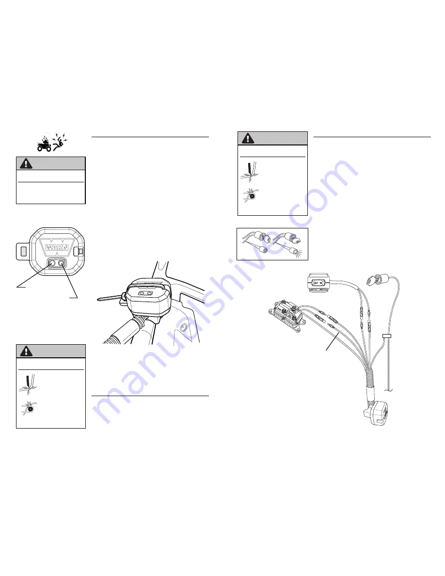
Programming LED
Programming button
STEP 3: ROUTE THE HARNESS
Locate the BLACK and GREEN wires running from the contactor
to the handlebar switch. Find the bullet connectors on these
wires located near the contactor.
Plan a route for the wire harness between the receiver and these
bullet connectors.
W A R N I N G
TO PREVENT SERIOUS INJURY OR DEATH
FROM EXPLOSION:
•
Do not drill into gas tank.
•
Verify the area is clear behind the
mounting location before drilling.
W A R N I N G
•
Never route electrical cables:
- Across any sharp edges.
- Through or near moving
parts.
- Near parts that become
hot.
•
Always insulate and protect all
exposed wiring and electrical
terminals.
TO AVOID SERIOUS INJURY OR DEATH
FROM ELECTRICAL FIRE:
STEP 4: CONNECT THE WIRING
Note:
Refer to Figure 1.
1. Pull apart the bullet connectors on the BLACK and GREEN
wires identified in Step 3 above. These will be located near
the contactor
2. Connect the BLACK and GREEN wires to the same color wires
on the wire harness as shown on the wiring diagram.
3. Connect the BLACK ground wire with the ring terminal to the
contactor as shown.
4. Using a test light, locate a switched accessory wire attached
to the ATV ignition system. The wire should only have power
when the key is in the “ON” position.
5. Splice the RED wire to the key controlled accessory wire using
the provided wire splice.
6. Use tie wraps to secure the wire harness
Use a test light to locate an
accessory circuit wire.
Figure 1: Wiring Installation Diagram
W A R N I N G
•
Never route electrical cables:
- Across any sharp edges.
- Through or near moving
parts.
- Near parts that become
hot.
•
Always insulate and protect all
exposed wiring and electrical
terminals.
TO AVOID SERIOUS INJURY OR DEATH
FROM ELECTRICAL FIRE:
Black
Green
Black
Red
Black
Green


